System for removing a clot from a blood vessel

a technology a blood vessel, which is applied in the field of systems for removing a clot from a blood vessel, can solve the problems of limited therapy options, difficulty in mechanical thrombectomy and/or revascularisation devices, and acute ischemic strok

Active Publication Date: 2015-12-31
NEURAVI
View PDF10 Cites 58 Cited by
  • Summary
  • Abstract
  • Description
  • Claims
  • Application Information

AI Technical Summary

Benefits of technology

[0009]In one embodiment the maximum diameter of the shaft proximal section is less than 0.003″ smaller than the inner distal lumen of the catheter distal section.
[0010]In one embodiment the maximum diameter of the shaft proximal section is less than 0.002″ smaller than the inner distal lumen of the catheter distal section.

Problems solved by technology

Acute ischemic stroke (AIS) is a worldwide problem for which until recently there have been only limited therapy options available for patients.
However it may be challenging for a mechanical thrombectomy and / or revascularisation device to pass through such a small diameter microcatheter.
One particular challenge involves the ability to push the device through the microcatheter, especially around tortuous bends in distal anatomies.
However if the device is to be used with a very small diameter microcatheter (as is desirable) then the diameter of the shaft is limited to a size somewhat smaller than the inner diameter of this microcatheter.
This trade-off between microcatheter profile and shaft profile means that conventional mechanical thrombectomy and / or revascularisation devices either a) are compatible with very small diameter microcatheters but suffer from having flimsy shafts which are easily damaged and cannot effectively transmit a push force to advance the device around significant tortuosity, or b) are fitted with sufficiently large diameter shafts to have good robustness and pushability but are not compatible with very small diameter microcatheters.
Without any clearance the shaft would not move freely through the catheter and would be very difficult to advance.
However this means compromising on the kink resistance and durability of the nitinol shaft.

Method used


Image

  • System for removing a clot from a blood vessel
  • System for removing a clot from a blood vessel
  • System for removing a clot from a blood vessel

Examples


Embodiment Construction

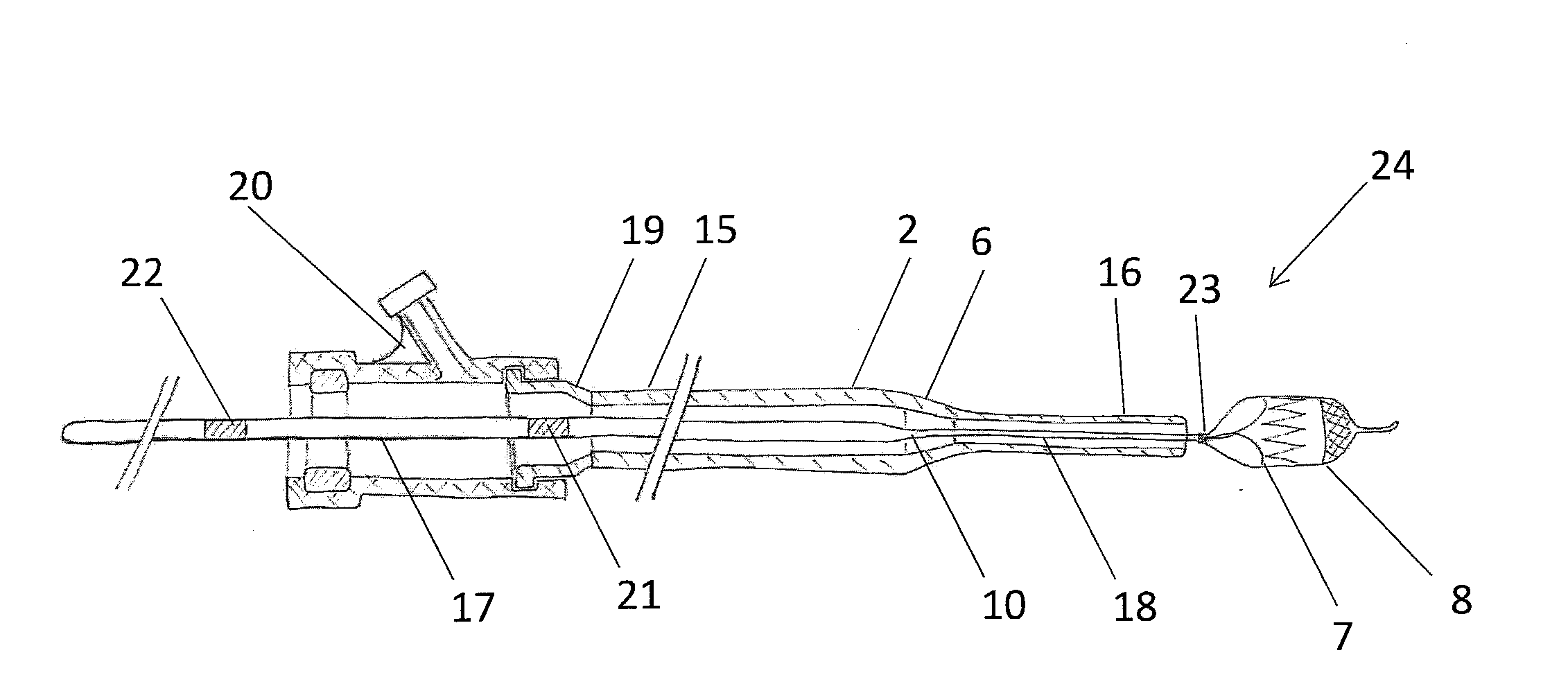
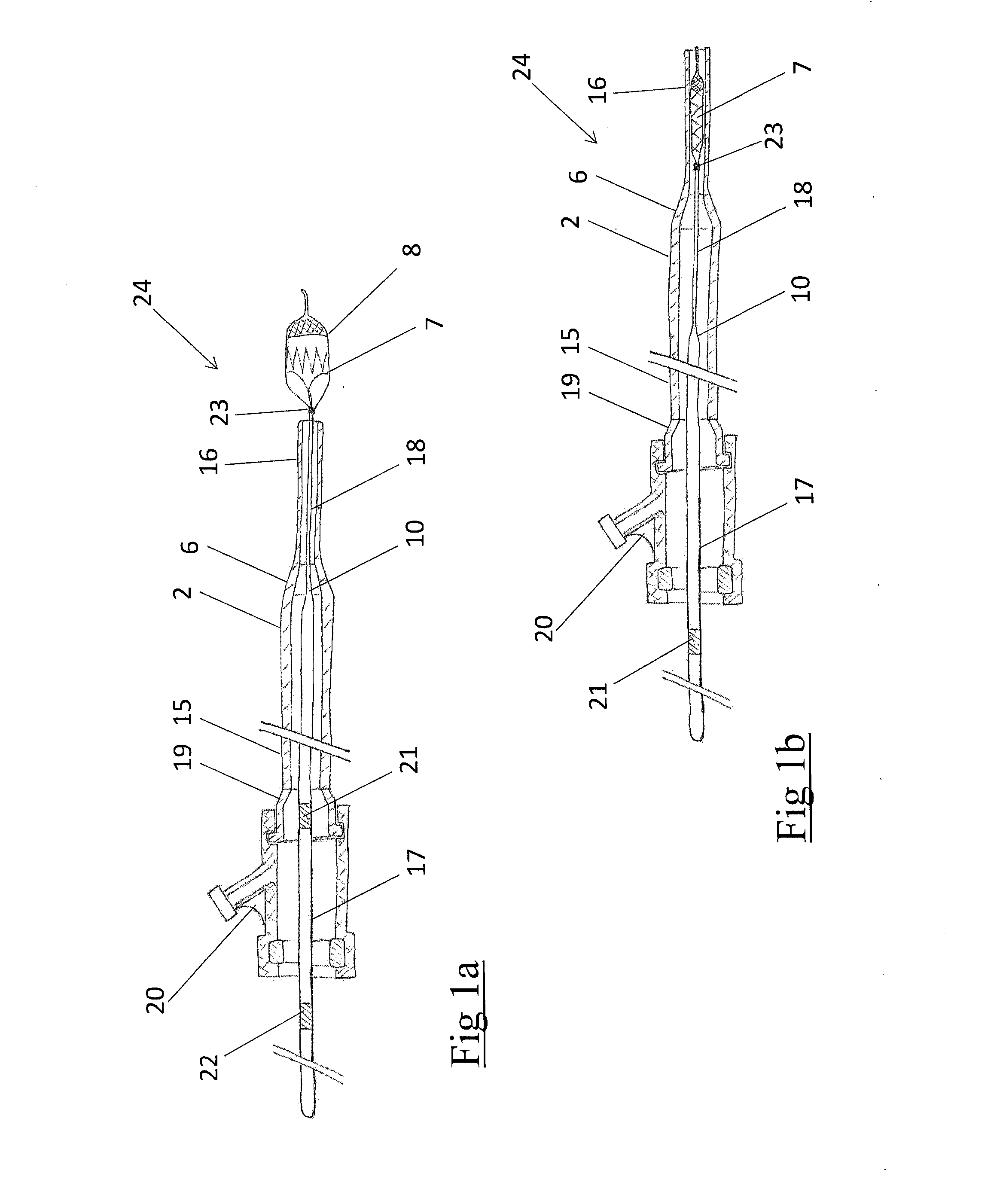
[0033]Referring to FIGS. 1a and 1b of the drawings there is illustrated a system 24 for removing obstructions such as clot from a blood vessel, the system comprising a clot retrieval device 8 having a clot retrieval element 7 mounted at the distal end of an elongate shaft 9 and a catheter 2 which in this case is a microcatheter which is used to deliver the clot retrieval element 7 in a collapsed delivery configuration across a clot. The clot retrieval element 7 is deployed from the catheter 2 into an expanded deployed configuration for clot retrieval. FIG. 1a shows the system with the clot retrieval element 7 in the deployed expanded condition. FIG. 1b shows the system with the clot retrieval element 7 collapsed within the distal portion 16 of the microcatheter 2, just prior to deployment.

[0034]The catheter 2 comprises a catheter proximal section 15, a catheter distal section 16, and a catheter intermediate section 6 between the proximal and distal section. The catheter distal secti...


PUM


Abstract

A system for removing obstructions from a blood vessel comprises a clot retrieval device and a catheter. The clot retrieval device comprises a clot engaging element attached to the distal end of an elongate shaft. The elongate shaft has a shaft proximal section, a shaft distal section and a shaft intermediate section between the shaft distal and proximal sections. The catheter has a catheter proximal section, a catheter distal section, and a catheter intermediate section between the proximal and distal sections. The maximum diameter of a shaft proximal section is greater than an inner distal lumen of the catheter distal section.

Description

CROSS REFERENCE TO RELATED APPLICATIONS [0001]This application claims the benefit of U.S. Provisional Application No. 62 / 019,137, filed Jun. 30, 2014, the entirety of which is incorporated herein by reference in its entirety.INTRODUCTION[0002]Acute ischemic stroke (AIS) is a worldwide problem for which until recently there have been only limited therapy options available for patients. One option for such patients is a lytic drug called tPa, which can be administered either intravenously or intra-arterially. More recently various mechanical thrombectomy and / or revascularisation devices have become available which aim to dislodge and remove the clot using mechanical means. These devices are typically advanced through a small catheter (called a microcatheter) to the site of the occlusive blood clot, whereupon they are deployed from this microcatheter and engaged with the clot. It would be advantageous for the patient and physician that this microcatheter be as flexible and small in dia...

Claims


Application Information

Patent Timeline
Patent Type & Authority Applications(United States)
IPC IPC(8): A61F2/01
CPCA61F2/013A61F2002/016A61B2017/2212A61B2017/22034A61B2017/22079A61B17/221
Inventor VALE, DAVID
Owner NEURAVI
Why Eureka
Try Eureka