
Cargo area of an airport

a technology for cargo and airports, applied in domestic applications, loading/unloading, storage devices, etc., can solve the problems of inability to synchronize delivery and further transportation, and achieve the effect of speeding up the storage and retrieval process

Inactive Publication Date: 2008-06-05
SIEMENS AG
View PDF29 Cites 2 Cited by
  • Summary
  • Abstract
  • Description
  • Claims
  • Application Information

AI Technical Summary

Benefits of technology

[0005]Taking as the departure point the abovedescribed disadvantages of current cargo areas, the object of the present invention is to create storage and sorting opportunities in the immediate vicinity of the transporting paths, while being simultaneously independent of the main store, in order to achieve flexible supply.
[0006]In order to achieve the object, the invention proposes that the transporting paths are directly assigned vertical stores each with a plurality of storage levels which are arranged one above the other, are set up above or alongside the transporting paths and in which, with the aid of lifting means, the cargo carriers, which can be lifted off from the transporting paths, can be stored. The vertical stores assigned to the transporting paths avoid high-outlay storage in the main store and allow very quick access to the cargo carriers buffer-stored there, along with simultaneous sorting opportunities.
[0007]It is considered to be particularly advantageous if, according to one configuration of the invention, the vertical stores can be isolated from the conveying flow of the loading units. This is because this isolation makes it possible to keep the transporting paths free of any loading units which are to be stored, in which case subsequent and preferential orders can be transported past the buffer-stored loading units and it is even possible for transporting paths to be used in both directions.

Problems solved by technology

In conventional airport cargo areas, it is not possible, as a result of the usually simple design of the bypass conveyor, for the transporting paths to be used simultaneously for transporting the ULDs in both directions.
Although the goods are often delivered in correspondence with their loading times (just in time), it is often not possible to synchronize delivery and further transportation.

Method used


Image

  • Cargo area of an airport
  • Cargo area of an airport
  • Cargo area of an airport

Examples


Embodiment Construction

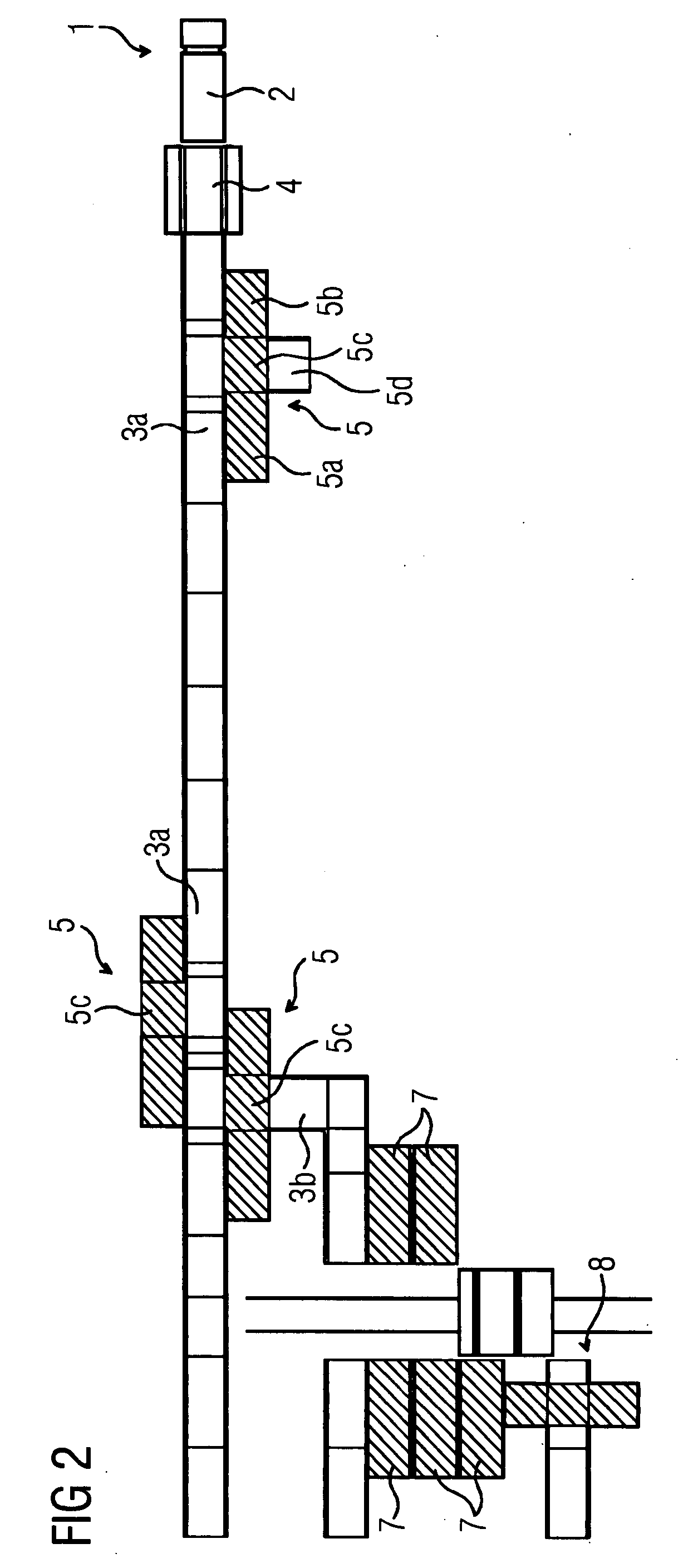
[0026]In the roughly schematic illustration of FIG. 1, 1 designates the land side of an airport, where trucks 2 deliver their cargo for further transportation on a transporting path 3a, for example a roller conveyor. Provided directly in the truck-unloading area is an arrangement for weighing and measuring the loading unit, which is usually constituted by so-called ULDs, which are standard containers for receiving the goods which are to be transported. The measuring apparatus is designated by 4. Immediately following the measuring apparatus 4 in FIG. 1 is a first vertical store 5, of which the lowermost level has the transporting path 3a running through it. This first vertical store 5 preferably serves for storing storage units which, coming from the air side, are intended for retrieval on the land side, and are thus buffer-stored in the vicinity of the truck-loading area in order to be capable of being loaded quickly. The vertical store comprises a plurality of storage levels 5a, 5...


PUM


Abstract

The invention relates to the cargo area of an airport, having transporting paths which connect the land side and the air side of the airport and are intended for the standard loading units (ULDs), and also having interim stores for the buffer storage of the loading units prior to the cargo being assembled. In order to create storage and sorting opportunities in the immediate vicinity of the transporting paths, while being simultaneously independent of the main store, and in order to achieve flexible supply of the loading units, it is proposed for the transporting paths to be assigned vertical stores each with a plurality of storage levels which are arranged one above the other, are set up above or alongside the transporting paths and in which, with the aid of lifting means, the loading units, which can be lifted off from the transporting paths, can be stored.

Description

CROSS REFERENCE TO RELATED APPLICATIONS[0001]This application claims priority of German Patent application No. 10 2006 046 691.8 filed Sep. 29, 2006, which is incorporated by reference herein in its entirety.FIELD OF INVENTION[0002]The invention relates to the cargo area of an airport, having a land side for connecting to the road and / or railroad and having an air side for connecting to the apron of the airport, and having transporting paths which connect the two sides and are intended for the standard loading units (ULDs) which are to be transported between the land side and air side, and also having interim stores for the buffer storage of the loading units within the cargo area prior to the cargo which is to be assigned to an aircraft or a vehicle in a desired order being assembled.BACKGROUND OF THE INVENTION[0003]In cargo areas of airports, goods are handled in so-called ULDs, which is the term used to refer to the standard transporting containers, these advantageously being ada...

Claims


Application Information

Patent Timeline
Patent Type & Authority Applications(United States)
IPC IPC(8): B64F1/32B65G67/00
CPCB65G63/025B65G1/04B65G63/004
Inventor WENZEL, REINHARD
Owner SIEMENS AG
Learn More