Retaining system and method for preventing the release of wires from a poke-in connector
a technology of wire retention and poke-in connector, which is applied in the direction of electrical equipment, contact members penetrating/cutting insulation/cable strands, coupling device connections, etc., can solve the problem of accidentally releasing wires, and achieve the effect of increasing stiffness, increasing stiffness, and increasing the thickness of the wire ti
- Summary
- Abstract
- Description
- Claims
- Application Information
AI Technical Summary
Benefits of technology
Problems solved by technology
Method used
Image
Examples
first embodiment
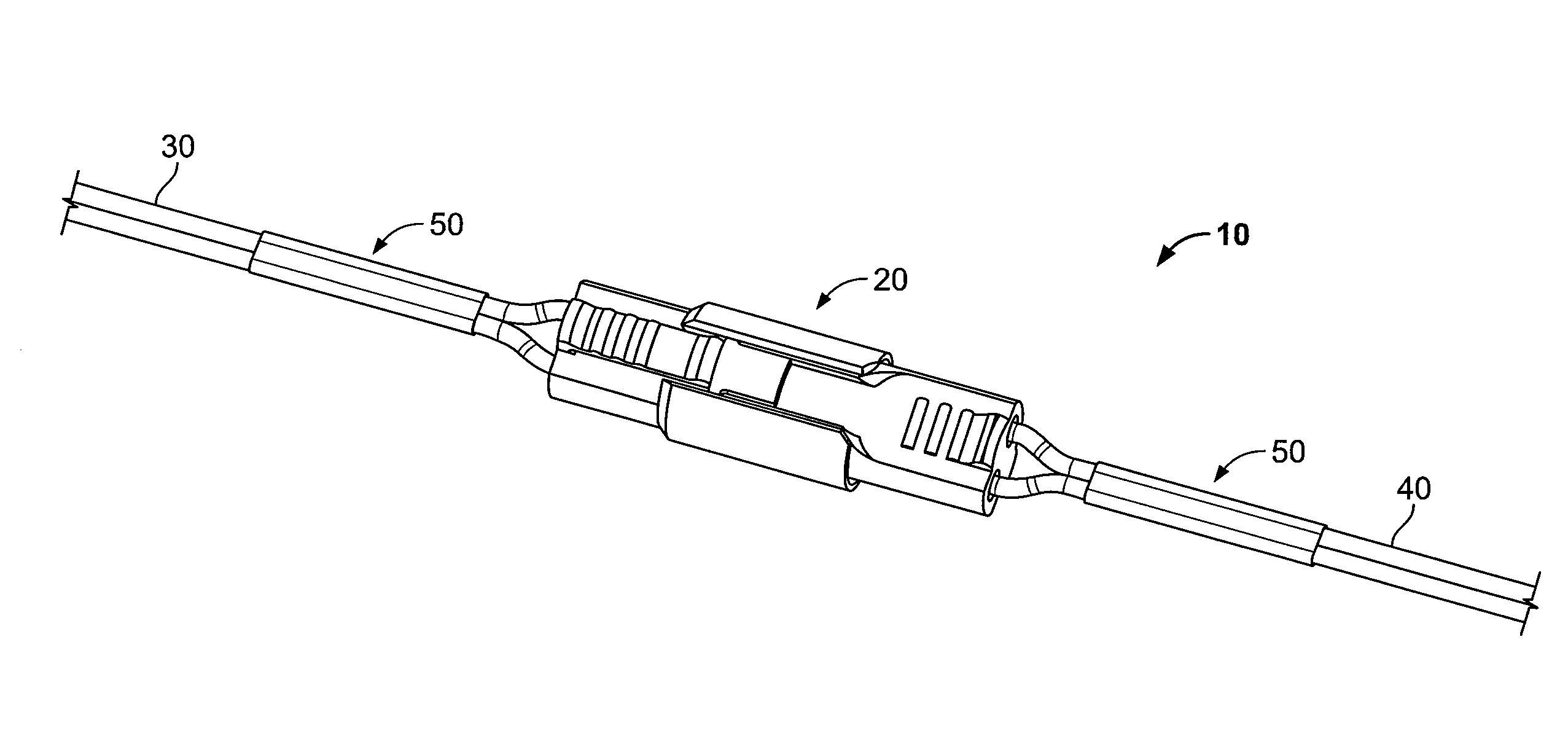
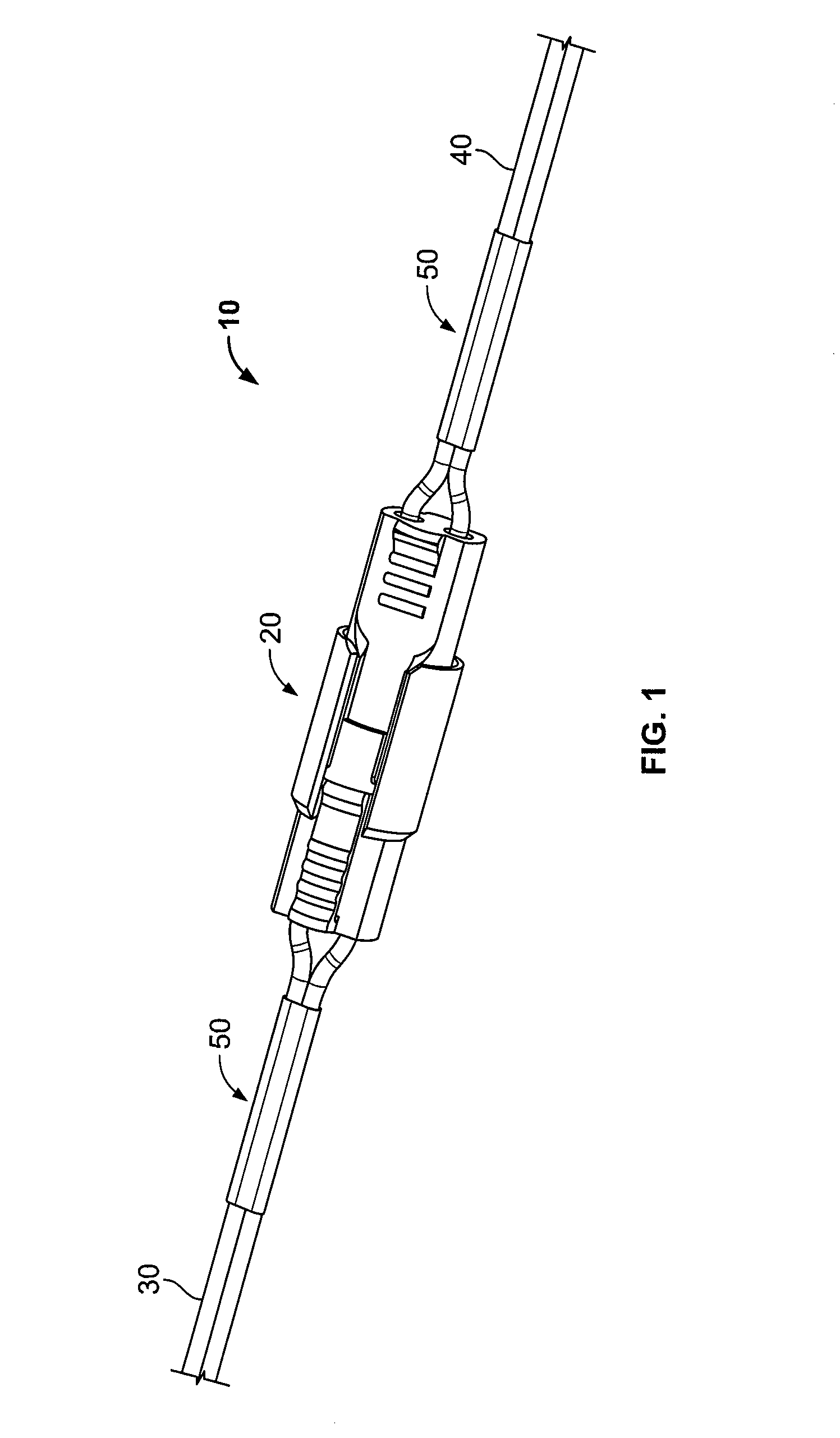
[0022]Referring to FIG. 1, according to the invention, a retaining system 10 for preventing the accidental release of two or more wires from a poke-in connector 20 is shown. The retaining system 10 includes a poke-in connector 20 for electrically connecting wires, input wires 30, output wires 40, and a pair of wire bundling sleeves 50. The input wires 30 and output wires 40 are formed of 18 gauge wire.
[0023]A first wire bundling sleeve 50 was placed around the input wires 30. A second wire bundling sleeve 50 was placed around the output wires 40. The sleeves were formed of 0.5 inches lengths of polyolefin tubing manufactured under the name ShrinkMark produced by Tyco Electronics Corporation of Middletown, Pa. The sleeves were slid over the wires and heated to shrink the sleeve securely around the wires. Both sleeves 50 were placed approximately 0.5 inches from the point where the input wires 30 and output wires 40 enter the connector 20.
[0024]The sleeves 50 prevented the input wires...
third embodiment
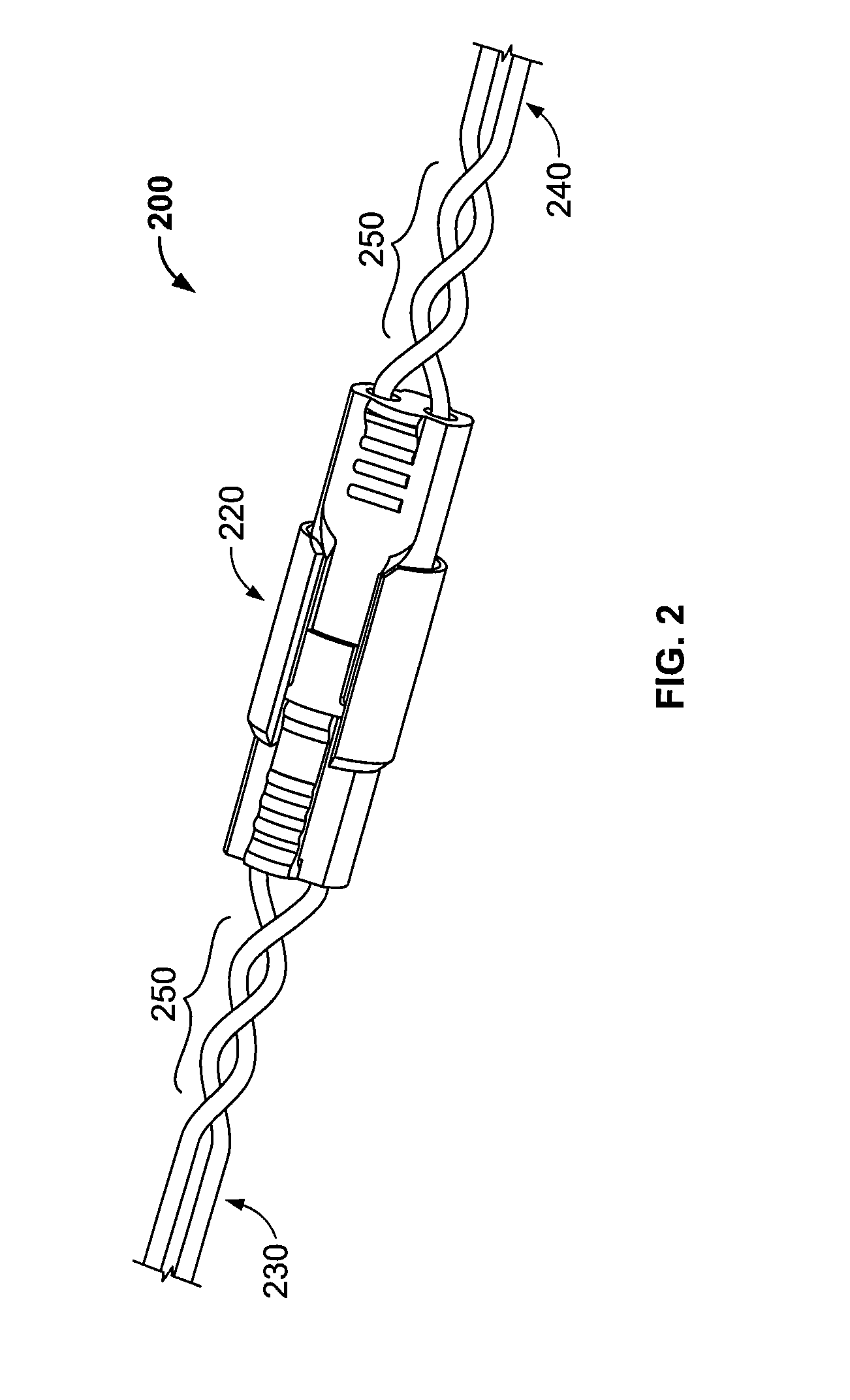
[0027]the invention is illustrated in FIG. 2. As shown in FIG. 2, a second retaining system 200 was formed of a poke in connector 220, input wires 230, output wires 240, and wire twist sections 250. The input wires 230 were prevented from disconnecting from the connector 220 by the wire twist section 250. The wire twist section 250 bundled the input wires 230 and output wires 240 proximate to a point where the wires entered the connector 220. The wire twist section 250 was formed by twisting two 18 gauge wires that formed the input wires 230 around one another twice proximate to the point where the input wires 230 entered the connector 220. The other wire twist section 250 was formed by twisting two 18 gauge wires that formed the output wires 230 proximate to the point where the output wires 240 entered the connector 220.
[0028]The wire twist sections prevented the input wires 230 and output wires 240 from substantially rotating proximate to the point where the wires enter the connec...
fourth embodiment
[0029]the invention is shown in FIG. 3. As illustrated in FIG. 3, a third retaining system 300 was formed of a poke-in connector 320, input wires 330, output wires 340, and a pair of wire bundling sleeves 350. A wire bundling sleeve 350 was placed around the input wires 330 and another wire bundling sleeve 350 was placed around the output wires 340 to prevent the wires form disconnecting from the connector 320 when the wires 340 are pulled in a direction away from the connector 320 while simultaneously twisted. The sleeve 350 incorporated an identifier 360 to mark the wires 330 that have been bundled. The identifier 360 was a label.
[0030]In this embodiment, the bundling sleeve 350 was formed of shrink wrap tubing incorporating the identifier 360 formed of a polyolefin tubing manufactured under the name ShrinkMark produced by Tyco Electronics Corporation of Middletown, Pa. The shrink wrap tubing forming the sleeve 350 was formed around the wires 330 by conventional sliding the sleeve...
PUM
 Abstract
Description
Claims
Application Information
 - R&D
- Intellectual Property
- Life Sciences
- Materials
- Tech Scout
- Unparalleled Data Quality
- Higher Quality Content
- 60% Fewer Hallucinations
Browse by: Latest US Patents, China's latest patents, Technical Efficacy Thesaurus, Application Domain, Technology Topic, Popular Technical Reports.
© 2025 PatSnap. All rights reserved.Legal|Privacy policy|Modern Slavery Act Transparency Statement|Sitemap|About US| Contact US: help@patsnap.com


