Electrode assembly for nerve control

a nerve and electrode technology, applied in the direction of internal electrodes, spinal electrodes, therapy, etc., can solve the problems of poor force gradation and muscle fatigue, and achieve the effect of reducing the magnitude of the (typically desired) hyperpolarization region, minimizing the depolarization portion, and reducing the magnitude of the hyperpolarization region

Active Publication Date: 2008-06-05
MEDTRONIC INC
View PDF12 Cites 103 Cited by
  • Summary
  • Abstract
  • Description
  • Claims
  • Application Information

AI Technical Summary

Benefits of technology

[0063]By contrast, it is desired when performing many of these applications to minimize the depolarization portion of the anodal activation function, because the location on the nerve of the depolarization portion corresponds to the location of the virtual cathode described hereinabove. If no countermeasures would be taken, the virtual cathode could be associated with an undesired stimulation of fibers in the nerve under the virtual cathode. The virtual cathode effect could be minimized to some extent by reducing the anodal current, but, if in excess, this would result in a decrease in the magnitude of the (typically desired) hyperpolarization region. If the anodal current is only minimally reduced, in order to avoid adversely decreasing the magnitude of the hyperpolarization region, then the virtual cathode effect would typically still be present. The inventors have determined that for many electrode configurations, there is no suitable balance, i.e., either the virtual cathode effect will be reduced to a desired level, or the hyperpolarization portion of the activation function will be maintained at a sufficiently high magnitude.
[0064]To address this issue, the plurality of anodes provided by these embodiments of the present invention are typically configured so as to have the maximum magnitude of the hyperpolarization portion be at least five times the maximum magnitude of the depolarization amplitude. In this manner, the desired hyperpolarization effect is preserved, and the extent of depolarization due to the anodal current is minimized. Typically, this ratio of anodally-induced hyperpolarization to depolarization is attained by using one or more of the following: (a) one or more secondary inhibiting anodes, as described hereinabove, to minimize the virtual cathode effect, (b) one or more insulating elements whose closest approach to the nerve generally remains further from the central axis of the nerve than approximately 1.5 times the radius of the nerve, or (c) electrodes, whose closest approach to the nerve generally remains further from the central axis of the nerve than approximately 1.5 times the radius of the nerve.

Problems solved by technology

This unnatural recruitment order causes muscle fatigue and poor force gradation.

Method used


Image

  • Electrode assembly for nerve control
  • Electrode assembly for nerve control
  • Electrode assembly for nerve control

Examples


Embodiment Construction

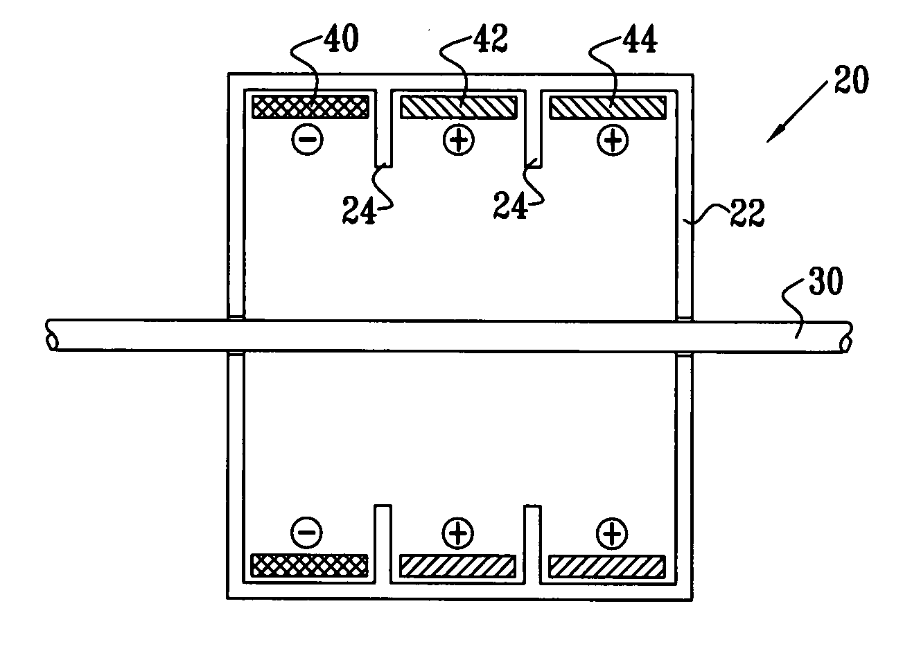
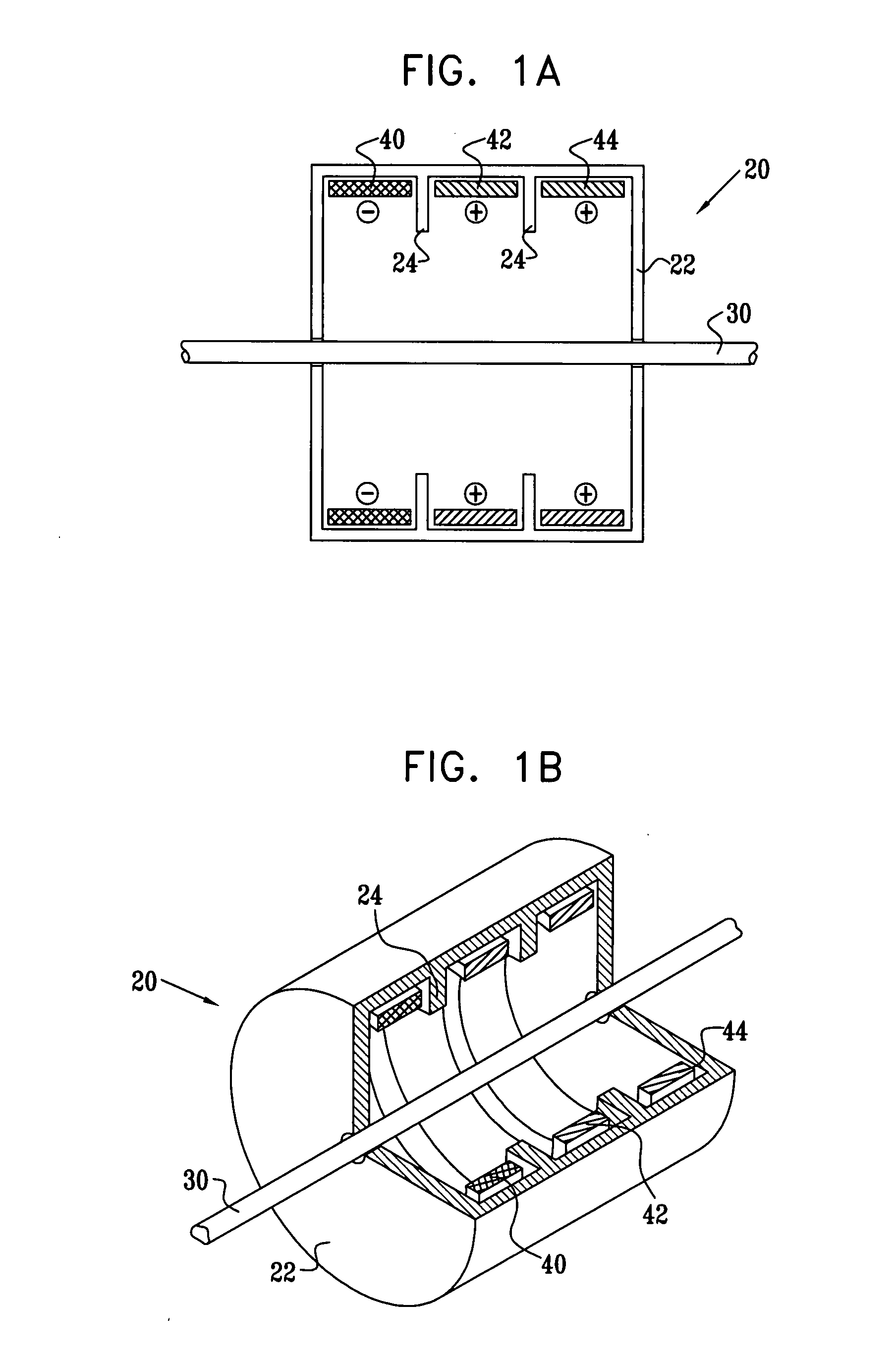
[0367]Reference is now made to FIGS. 1A and 1B. FIG. 1A is a schematic, cross-sectional illustration of an electrode assembly 20 for applying current to a nerve 30, in accordance with an embodiment of the present invention. FIG. 1B is a schematic pictorial illustration of electrode assembly 20, in accordance with an embodiment of the present invention. It is noted that although the various electrode assemblies shown in the figures generally contain cylindrical configurations of their elements, other geometrical configurations, such as non-rotationally symmetric configurations, are also suitable for applying the principles of the present invention. In particular, a housing 22 of the electrode assembly (and the electrodes themselves) may form a complete circle around the nerve, or it may define an arc between approximately 0 and 90 degrees, between 90 and 180 degrees, between 180 and 350 degrees, or between 350 and 359 degrees around the nerve. (One such embodiment, shown in FIG. 1B, ...


PUM


Abstract

Apparatus is provided for applying current to a nerve, including a housing, configured to be placed in a vicinity of the nerve. At least one electrode is fixed to the housing such that the at least one electrode does not come in direct physical contact with the nerve when the housing is placed in the vicinity of the nerve, and such that the electrode surrounds greater than 180 degrees of a circumference of the nerve after the placement of the housing. Two end insulating elements are fixed to the housing such that the at least one electrode is between the end insulating elements, and the end insulating elements come in contact or practically in contact with the nerve when the housing is placed in the vicinity of the nerve. Other embodiments are also described.

Description

CROSS-REFERENCES TO RELATED APPLICATIONS[0001]The present patent application is a continuation-in-part of: (a) U.S. patent application Ser. No. 11 / 022,011 to Cohen et al., filed Dec. 22, 2004, entitled, “Construction of electrode assembly for nerve control,” and (b) U.S. patent application Ser. No. 10 / 866,601 to Ben-Ezra et al., filed Jun. 10, 2004, entitled, “Applications of vagal stimulation.” Both of the above-mentioned patent applications are assigned to the assignee of the present patent application and are incorporated herein by reference.FIELD OF THE INVENTION[0002]The present invention relates generally to electrical stimulation of tissue, and specifically to methods and devices for regulating the stimulation of nerves.BACKGROUND OF THE INVENTION[0003]As defined by Rattay, in the article, “Analysis of models for extracellular fiber stimulation,” IEEE Transactions on Biomedical Engineering, Vol. 36, no. 2, p. 676, 1989, which is incorporated herein by reference, the activatio...

Claims


Application Information

Patent Timeline
Patent Type & Authority Applications(United States)
IPC IPC(8): A61N1/05
CPCA61N1/0551A61N1/36114A61N1/0556
Inventor COHEN, EHUDBEN-DAVID, TAMIRAYAL, SHAIBEN-EZRA, OMRY
Owner MEDTRONIC INC
Why Eureka
Try Eureka