
Electrode assembly for nerve control

a nerve control and electrode technology, applied in the field of tissue electrical stimulation, can solve the problems of muscle fatigue and poor force gradation, and achieve the effects of reducing the magnitude of the (typically desired) hyperpolarization region, minimizing the depolarization portion, and reducing the magnitude of the hyperpolarization region

Inactive Publication Date: 2005-02-17
MEDTRONIC INC
View PDF98 Cites 68 Cited by
  • Summary
  • Abstract
  • Description
  • Claims
  • Application Information

AI Technical Summary

Benefits of technology

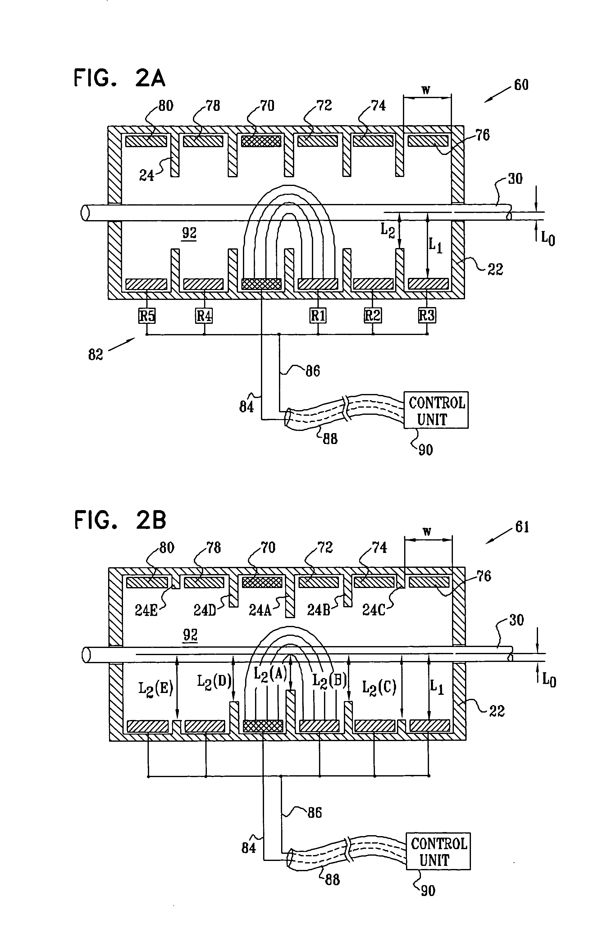
For most applications, the secondary anodal current is of lower magnitude than the primary anodal current. In this manner, the “virtual cathode” effect induced by the primary anodal current is minimized. As described in the Background section of the present patent application, the virtual cathode effect can stimulate—rather than block—the generation of action potentials in fibers in a region adjacent to the application of anodal current of a sufficiently high magnitude. In accordance with a preferred embodiment of the present invention, application of the primary and secondary anodal currents in appropriate ratios is configured to generally minimize the virtual cathode effect. Typically, but not necessarily, the ratio of the primary to the secondary anodal current ranges from 5:1 to 10:1.
In a preferred embodiment, a tertiary inhibiting anode is employed to reduce any virtual cathode effect which may be induced by the secondary inhibiting anode. For example, relative to a normalized cathodic current of −1, the primary inhibiting anode, secondary inhibiting anode, and tertiary inhibiting anode may be configured to apply respective currents of 0.66, 0.25, and 0.09. For some applications, the various anodes are independently driven by a control unit, so as to optimize the minimization of the virtual cathode effect and the maximization (when appropriate) of the anodally-induced hyperpolarization. Alternatively, fixed ratios are pre-defined for the currents applied by the anodes, and are set in hardware, e.g., by a set of resistors which link a single lead coming from the control unit to the respective anodes.
In a preferred embodiment, a secondary fiber-selection anode is also incorporated into the housing, adjacent to the primary fiber-selection anode and on the far side of the cathode. (Thus, the sequence of electrodes in the housing is: secondary fiber-selection anode, primary fiber-selection anode, cathode, primary inhibiting anode, secondary inhibiting anode.) In a fashion analogous to that described hereinabove with respect to the secondary inhibiting anode, the secondary fiber-selection anode is preferably driven to apply a current to the nerve smaller than that applied by the primary fiber-selection anode, so as to counteract the virtual cathode effect which would otherwise, in some circumstances, induce action potential propagation responsive to the current applied by the primary fiber-selection anode.
In preferred embodiments of the present invention, an electrode assembly for applying current to a nerve having a longitudinal axis comprises a housing, adapted to be placed in a vicinity of the nerve and a cathode and an anode, fixed to the housing. The cathode and anode are attached to the housing such that, when the housing is placed in the vicinity of the nerve, both the distance of the cathode and the distance of the anode to the axis are at least approximately 1.5 times greater than the radius of the nerve. By placing the cathode and anode at such a distance, increased electrical field uniformity is obtained within the nerve. In particular, the activation function (as defined in the Background section of this application) varies only relatively little across the cross-section of the nerve. This, in turn, increases the ability of a control unit driving the cathode and anode to assure that most fibers within the nerve will experience generally the same level of applied currents.
When there are three or more electrodes, thereby defining a ring of electrodes, the control unit preferably cycles around the electrodes in accordance with a stimulation protocol. For example, one such protocol for three electrodes may include driving current between electrodes 1 and 2, then 2 and 3, then 3 and 1, then 1 and 2, etc., cycling through the combinations at an electrode-pair transition average rate of greater than 1000 Hz, or, for some applications, greater than 10,000 Hz. For larger numbers of electrodes, e.g., 6, 12, or 24, the stimulation cycling protocol is typically more complex, and is preferably configured to cause current to pass through or close to most or all fibers in the nerve at the longitudinal site where the ring of electrodes is placed. One such complex protocol includes effectively creating a star out of the current lines passing through the nerve, or ensuring that each electrode in the ring conveys current to some, most, or all of the other electrodes.
Preferably, the apparatus includes a housing to which the cathode and the plurality of anodes are coupled, and one of the anodes is positioned within the housing so as to reduce a virtual cathode effect induced by another one of the anodes.

Problems solved by technology

This unnatural recruitment order causes muscle fatigue and poor force gradation.

Method used


Image

  • Electrode assembly for nerve control
  • Electrode assembly for nerve control
  • Electrode assembly for nerve control

Examples


Embodiment Construction

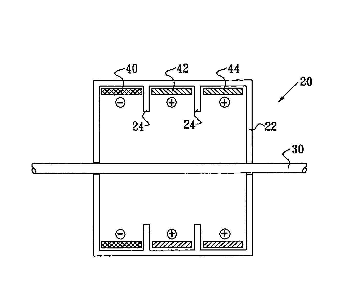
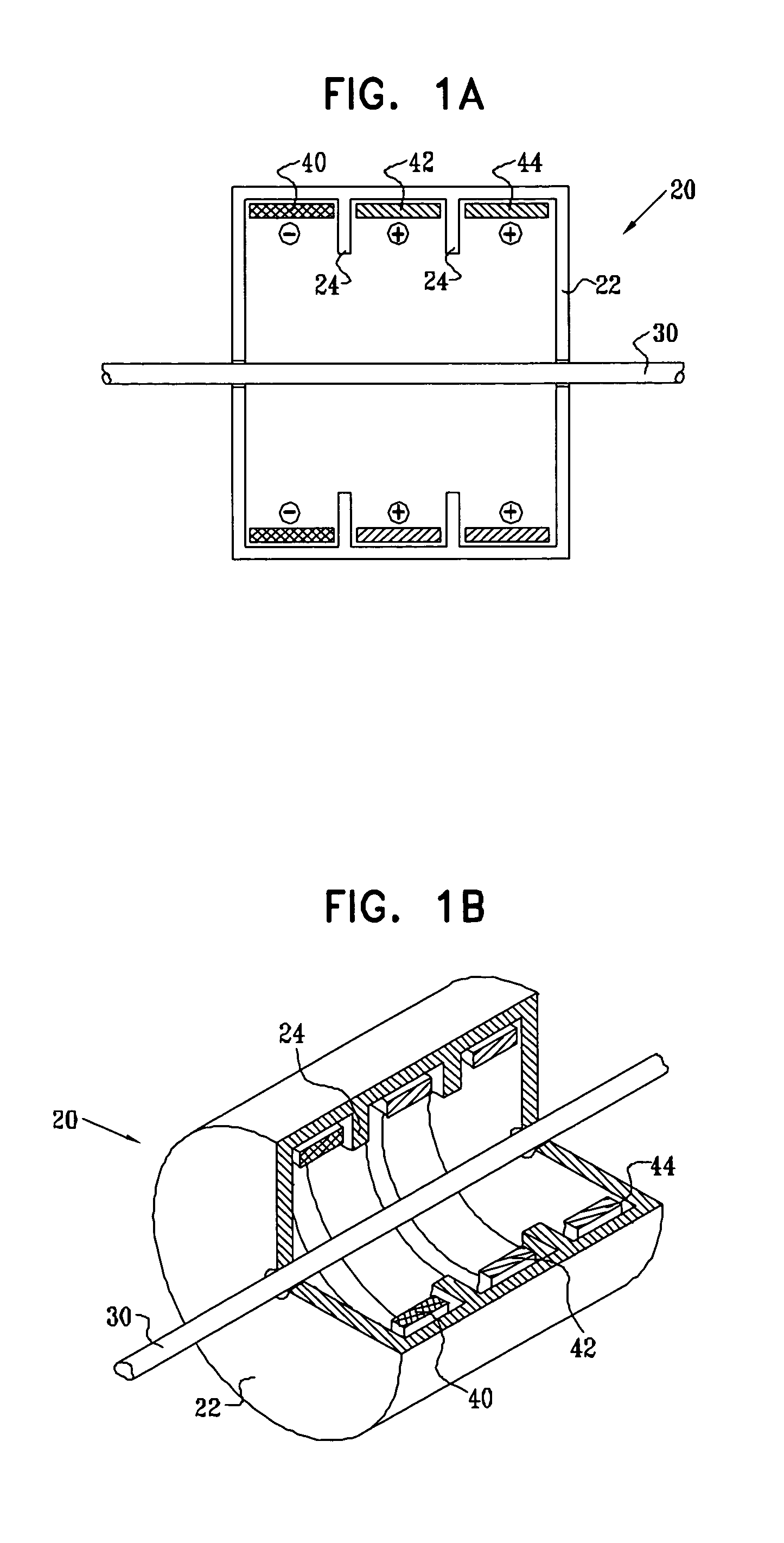
Reference is now made to FIGS. 1A and 1B. FIG. 1A is a schematic, cross-sectional illustration of an electrode assembly 20 for applying current to a nerve 30, in accordance with a preferred embodiment of the present invention. FIG. 1B is a schematic pictorial illustration of electrode assembly 20, in accordance with a preferred embodiment of the present invention. It is noted that although the various electrode assemblies shown in the figures generally contain cylindrical configurations of their elements, other geometrical configurations, such as non-rotationally symmetric configurations, are also suitable for applying the principles of the present invention. In particular, a housing 22 of the electrode assembly (and the electrodes themselves) may form a complete circle around the nerve, or it may define an arc between approximately 0 and 90 degrees, between 90 and 180 degrees, between 180 and 350 degrees, or between 350 and 359 degrees around the nerve. (One such preferred embodim...


PUM


Abstract

Apparatus is provided for applying current to a nerve. A cathode is adapted to be placed in a vicinity of a cathodic longitudinal site of the nerve and to apply a cathodic current to the nerve. A primary inhibiting anode is adapted to be placed in a vicinity of a primary anodal longitudinal site of the nerve and to apply a primary anodal current to the nerve. A secondary inhibiting anode is adapted to be placed in a vicinity of a secondary anodal longitudinal site of the nerve and to apply a secondary anodal current to the nerve, the secondary anodal longitudinal site being closer to the primary anodal longitudinal site than to the cathodic longitudinal site.

Description

FIELD OF THE INVENTION The present invention relates generally to electrical stimulation of tissue, and specifically to methods and devices for regulating the stimulation of nerves. BACKGROUND OF THE INVENTION As defined by Rattay, in the article, “Analysis of models for extracellular fiber stimulation,” IEEE Transactions on Biomedical Engineering, Vol. 36, no. 2, p. 676, 1989, which is incorporated herein by reference, the activation function (AF) is the second spatial derivative of the electric potential along an axon. In the region where the activation function is positive, the axon depolarizes, and in the region where the activation function is negative, the axon hyperpolarizes. If the activation function is sufficiently positive, then the depolarization will cause the axon to generate an action potential; similarly, if the activation function is sufficiently negative, then local blocking of action potentials transmission occurs. The activation function depends on the current ...

Claims


Application Information

Patent Timeline
Patent Type & Authority Applications(United States)
IPC IPC(8): A61NA61N1/05A61N1/34A61N1/36A61N1/362
CPCA61N1/0551A61N1/0556A61N1/36114A61N1/36071A61N1/36007
Inventor GROSSAYAL, SHAICOHEN, EHUD
Owner MEDTRONIC INC
Learn More