
Construction of electrode assembly for nerve control

a nerve control and electrode technology, applied in the direction of internal electrodes, spinal electrodes, therapy, etc., can solve the problems of poor force gradation and muscle fatigue, and achieve the effect of reducing the magnitude of the (typically desired) hyperpolarization region, minimizing the depolarization portion, and minimizing the virtual cathode

Inactive Publication Date: 2006-06-22
MEDTRONIC INC
View PDF98 Cites 85 Cited by
  • Summary
  • Abstract
  • Description
  • Claims
  • Application Information

AI Technical Summary

Benefits of technology

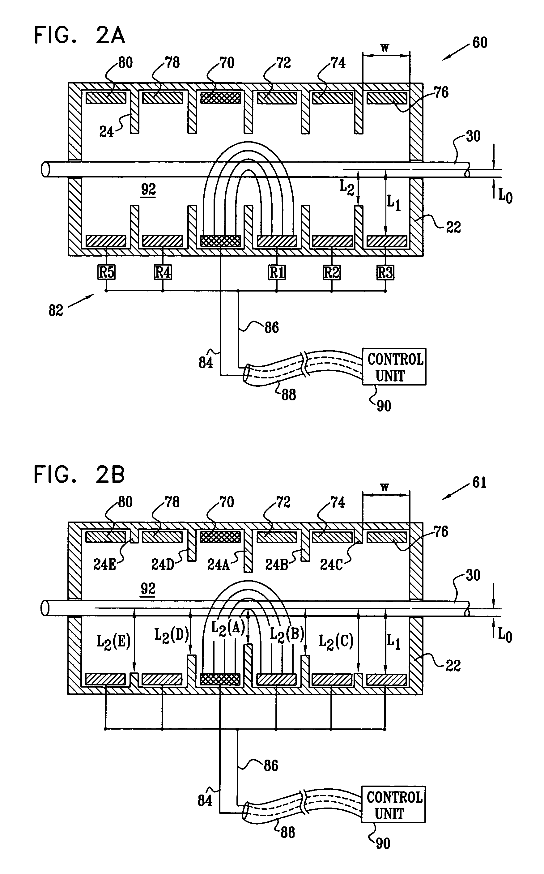
[0053] For most applications, the secondary anodal current is of lower magnitude than the primary anodal current. In this manner, the “virtual cathode” effect induced by the primary anodal current is minimized. As described in the Background section of the present patent application, the virtual cathode effect can stimulate—rather than block—the generation of action potentials in fibers in a region adjacent to the application of anodal current of a sufficiently high magnitude. In accordance with an embodiment of the present invention, application of the primary and secondary anodal currents in appropriate ratios is configured to generally minimize the virtual cathode effect. Typically, but not necessarily, the ratio of the primary to the secondary anodal current ranges from 5:1 to 10:1.
[0156] In an embodiment, the first edge includes a flap, adapted to come in contact with a portion of the cuff in the vicinity of the second edge when the first and second edges are held together. For some applications, when no external force is applied to the cuff, the flap forms an angle of between about 90 and about 180 degrees with a surface of the cuff in the vicinity of the first edge. For some applications, the flap includes a tab, configured to help draw the protrusion through the hole when the tab is moved toward the protrusion.

Problems solved by technology

This unnatural recruitment order causes muscle fatigue and poor force gradation.

Method used


Image

  • Construction of electrode assembly for nerve control
  • Construction of electrode assembly for nerve control
  • Construction of electrode assembly for nerve control

Examples


Embodiment Construction

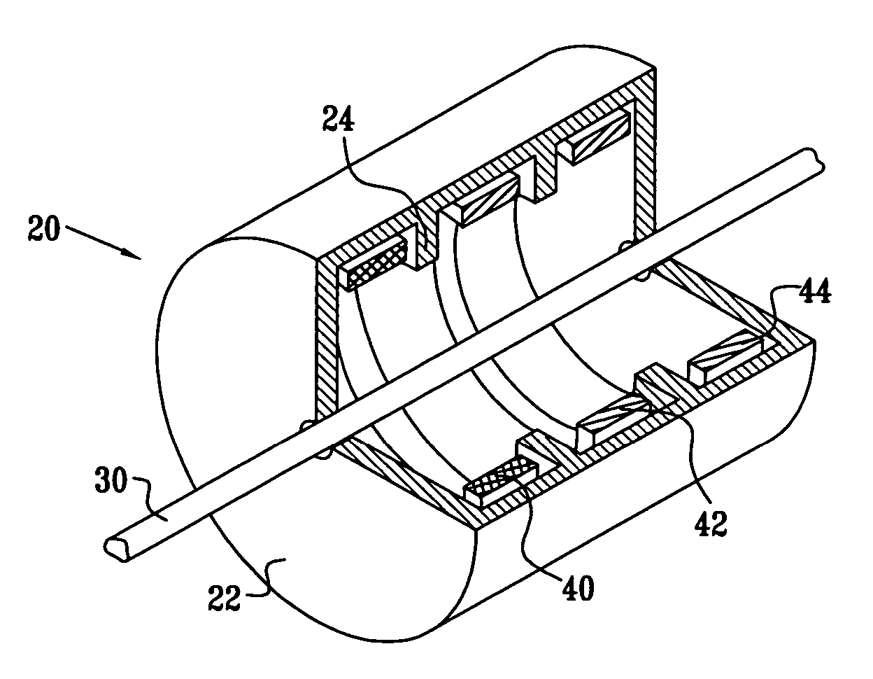
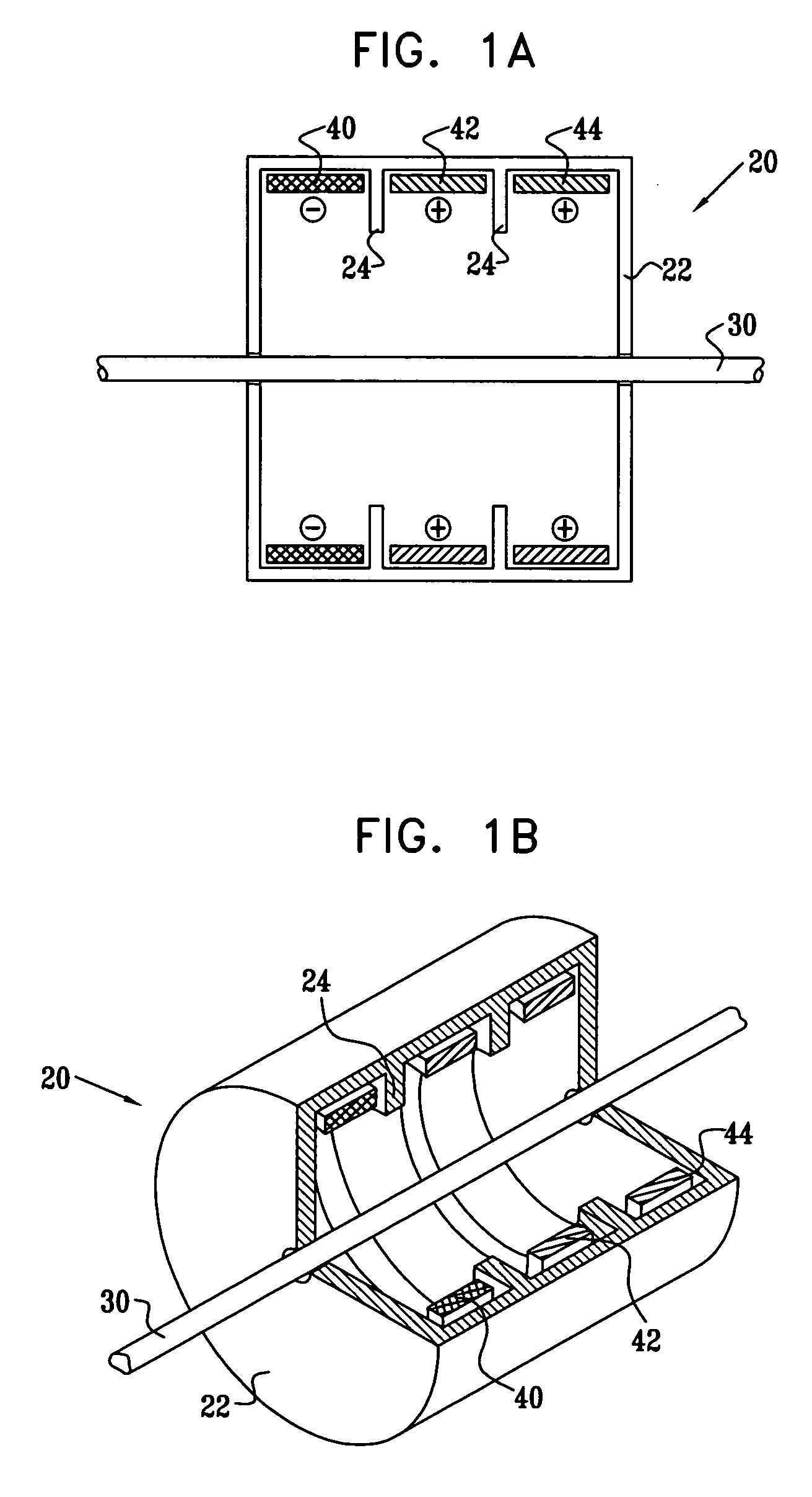
[0363] Reference is now made to FIGS. 1A and 1B. FIG. 1A is a schematic, cross-sectional illustration of an electrode assembly 20 for applying current to a nerve 30, in accordance with an embodiment of the present invention. FIG. 1B is a schematic pictorial illustration of electrode assembly 20, in accordance with an embodiment of the present invention. It is noted that although the various electrode assemblies shown in the figures generally contain cylindrical configurations of their elements, other geometrical configurations, such as non-rotationally symmetric configurations, are also suitable for applying the principles of the present invention. In particular, a housing 22 of the electrode assembly (and the electrodes themselves) may form a complete circle around the nerve, or it may define an arc between approximately 0 and 90 degrees, between 90 and 180 degrees, between 180 and 350 degrees, or between 350 and 359 degrees around the nerve. (One such embodiment, shown in FIG. 1B,...


PUM


Abstract

Apparatus is provided for applying current to a nerve, including a housing that is adapted to be placed in a vicinity of the nerve. First, second, and third electrodes are fixed to the housing at first, second, and third longitudinal sites of the housing, respectively. The first, second, and third electrodes do not come in direct physical contact with the nerve. The second site is between the first and third sites. The second electrode has an electrode surface axial length. The apparatus also includes first and second internal insulating elements, which are fixed to the housing between the first and second longitudinal sites, and between the second and third longitudinal sites, respectively. The first and second internal insulating elements are shaped so as to define, upon placement of the housing, a nerve axial distance between the first and second internal insulating elements that is less than the electrode surface axial length.

Description

FIELD OF THE INVENTION [0001] The present invention relates generally to electrical stimulation of tissue, and specifically to methods and devices for regulating the stimulation of nerves. BACKGROUND OF THE INVENTION [0002] As defined by Rattay, in the article, “Analysis of models for extracellular fiber stimulation,” IEEE Transactions on Biomedical Engineering, Vol. 36, no. 2, p. 676, 1989, which is incorporated herein by reference, the activation function (AF) is the second spatial derivative of the electric potential along an axon. In the region where the activation function is positive, the axon depolarizes, and in the region where the activation function is negative, the axon hyperpolarizes. If the activation function is sufficiently positive, then the depolarization will cause the axon to generate an action potential; similarly, if the activation function is sufficiently negative, then local blocking of action potentials transmission occurs. The activation function depends on ...

Claims


Application Information

Patent Timeline
Patent Type & Authority Applications(United States)
IPC IPC(8): A61N1/05
CPCA61N1/0556
Inventor COHEN, EHUDBEN-DAVID, TAMIRAYAL, SHAIBEN-EZRA, OMRY
Owner MEDTRONIC INC
Learn More