Dissolvable electrode device

a technology of electrodes and electrodes, applied in the field of treating patients, can solve the problems of reduced cardiac output and/or a feeling of palpitation of patients, heart block, bradycardia, etc., and achieve the effect of reducing the magnitude of the (typically desired) hyperpolarization region, minimizing the depolarization portion, and reducing the magnitude of the virtual cathode

Inactive Publication Date: 2014-07-31
MEDTRONIC INC
View PDF0 Cites 54 Cited by
  • Summary
  • Abstract
  • Description
  • Claims
  • Application Information

AI Technical Summary

Benefits of technology

[0128]By contrast, it is desired when performing many of these applications to minimize the depolarization portion of the anodal activation function, because the location on the nerve of the depolarization portion corresponds to the location of the virtual cathode described hereinabove. If no countermeasures would be taken, the virtual cathode could be associated with an undesired stimulation of fibers in the nerve under the virtual cathode. The virtual cathode effect could be minimized to some extent by reducing the anodal current, but, if in excess, this would result in a decrease in the magnitude of the (typically desired) hyperpolarization region. If the anodal current is only minimally reduced, in order to avoid adversely decreasing the magnitude of the hyperpolarization region, then the virtual cathode effect would typically still be present. The inventors have determined that for many electrode configurations, there is no suitable balance, i.e., either the virtual cathode effect will be reduced to a desired level, or the hyperpolarization portion of the activation function will be maintained at a sufficiently high magnitude.
[0129]To address this issue, the plurality of anodes provided by these embodiments of the present invention are preferably configured so as to have the maximum magnitude of the hyperpolarization portion be at least five times greater than the maximum magnitude of the depolarization amplitude. In this manner, the desired hyperpolarization effect is preserved, and the extent of depolarization due to the anodal current is minimized. Preferably, this ratio of anodally-induced hyperpolarization to depolarization is attained by using one or more of the following: (a) one or more secondary inhibiting anodes, as described hereinabove, to minimize the virtual cathode effect, (b) one or more insulating elements whose closest approach to the nerve generally remains further from the central axis of the nerve than approximately 1.5 times the radius of the nerve, or (c) electrodes, whose closest approach to the nerve generally remains further from the central axis of the nerve than approximately 1.5 times the radius of the nerve.

Problems solved by technology

Because of this rapid and irregular rate, the patient suffers from reduced cardiac output and / or a feeling of palpitations.
Potential adverse effects of these drugs include hypotension, heart block, heart failure, and bradycardia.

Method used


Image

  • Dissolvable electrode device
  • Dissolvable electrode device
  • Dissolvable electrode device

Examples


Embodiment Construction

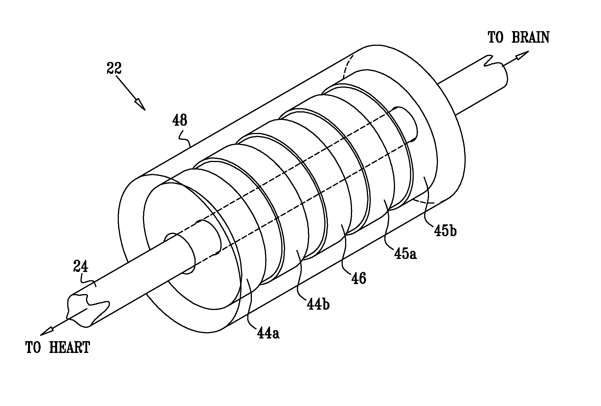
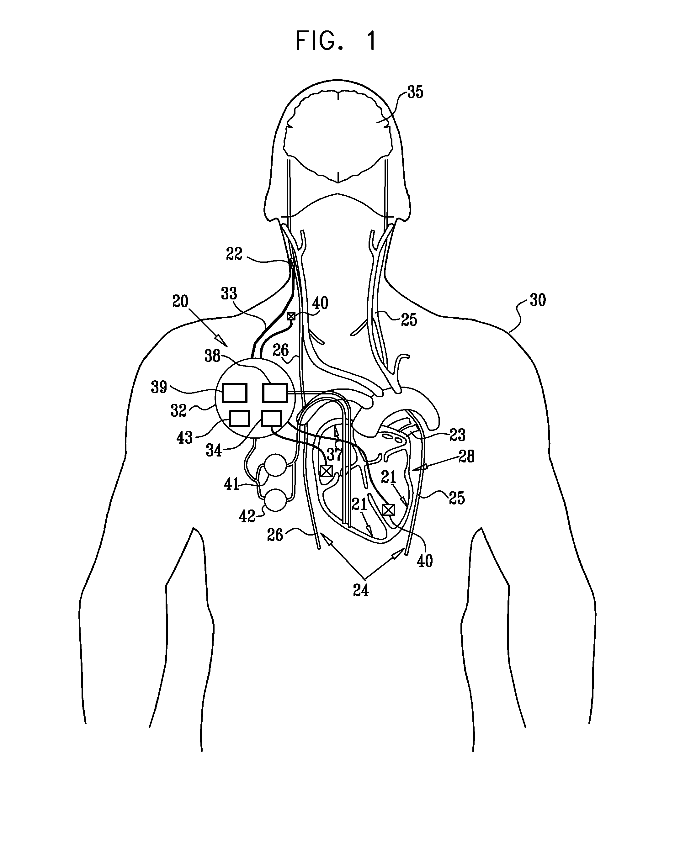
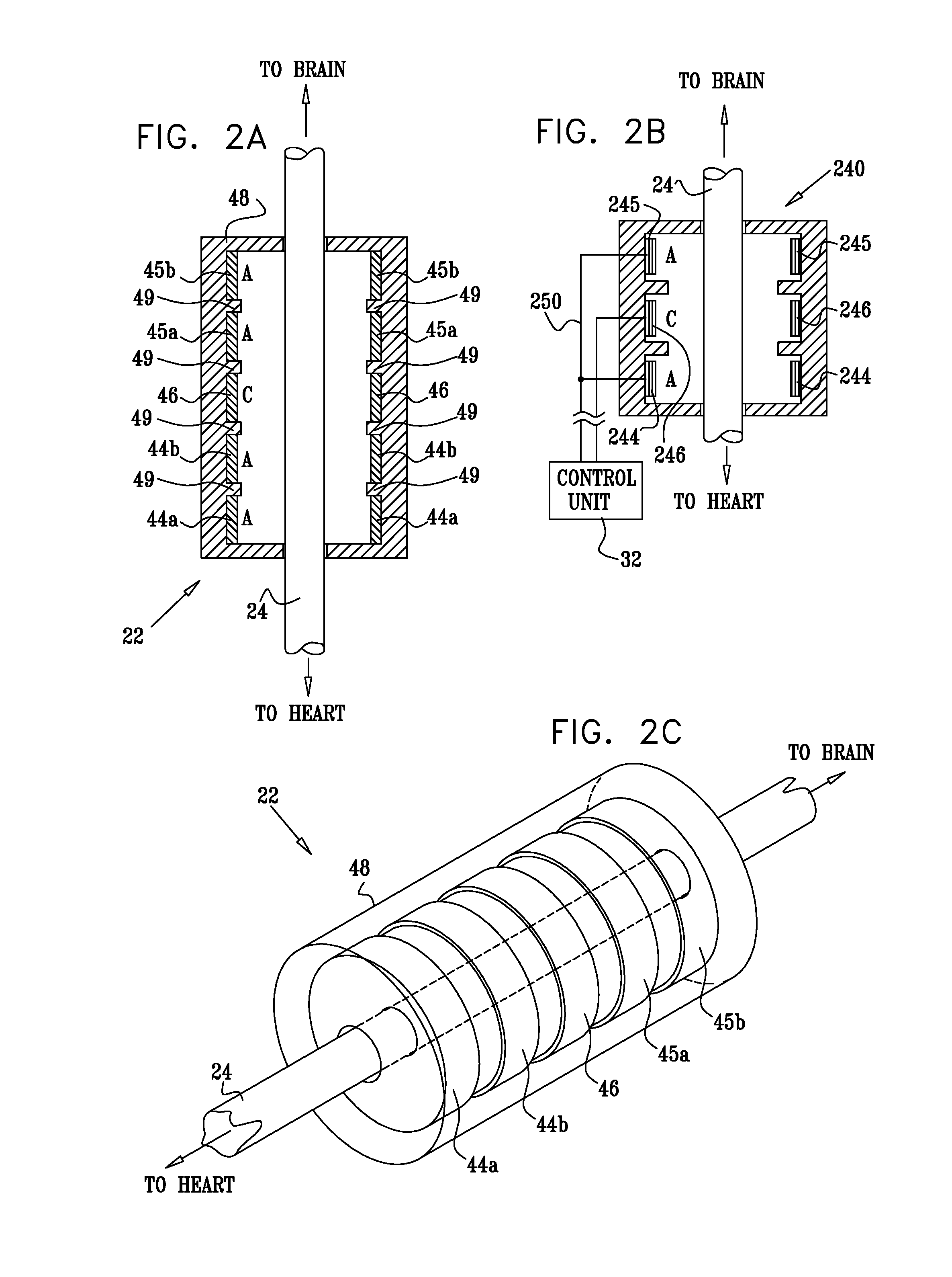
[1120]FIG. 1 is a schematic illustration of apparatus 20 for treating a subject 30, in accordance with an embodiment of the present invention. Apparatus 20 comprises at least one electrode device 22, which is applied to a site of the subject selected from the group consisting of: a vagus nerve 24 (either a left vagus nerve 25 or a right vagus nerve 26), which innervates a heart 28 of subject 30, an epicardial fat pad (e.g., a sinoatrial (SA) node fat pad, or an atrioventricular (AV) node fat pad), a pulmonary vein, a carotid artery, a carotid sinus, a coronary sinus, a vena cava vein, a jugular vein, an azygos vein, an innominate vein, and a subclavian vein. Alternatively or additionally, the site is selected from the group consisting of: a right ventricle, a right atrium, and other parasympathetic tissue that innervates heart 28. “Vagus nerve,” and derivatives thereof, as used in the present application including the claims, is to be understood to include portions of the left vagus...


PUM


Abstract

An electrode assembly is provided that is configured to be coupled to nervous tissue of a subject, the electrode assembly including one or more conductive elements. At least a portion of the electrode assembly, including the conductive elements, is configured to be dissolvable after the electrode assembly has been coupled to the tissue. The electrode assembly is configured to come loose from the tissue upon dissolving of the dissolvable at least a portion thereof. Other embodiments are also described.

Description

CROSS-REFERENCES TO RELATED APPLICATIONS[0001]The present application is a continuation-in-part of U.S. patent application Ser. No. 13 / 493,499, filed Jun. 11, 2012, which is a continuation-in-part of U.S. patent application Ser. No. 11 / 657,784, filed Jan. 24, 2007, now U.S. Pat. No. 8,204,591, and which is a continuation-in-part of:[0002](a) U.S. patent application Ser. No. 10 / 866,601, filed Jun. 10, 2004, now abandoned, which published as US Patent Application Publication 2005 / 0065553, and which claims the benefit of claims of U.S. Provisional Patent Application 60 / 478,576, filed Jun. 13, 2003;[0003](b) U.S. patent application Ser. No. 10 / 560,654, filed May 1, 2006, now U.S. Pat. No. 7,885,711, which is the U.S. national stage of PCT Patent Application PCT / IL04 / 00496, filed Jun. 10, 2004, which published as PCT Publication WO 04 / 110550, which is a continuation-in-part of U.S. patent application Ser. No. 10 / 461,696, filed Jun. 13, 2003, now U.S. Pat. No. 7,321,793; and[0004](c) U.S....

Claims


Application Information

Patent Timeline
Patent Type & Authority Applications(United States)
IPC IPC(8): A61N1/05A61N1/36
CPCA61N1/36114A61N1/0551A61N1/0556A61N1/36117A61N1/3621A61N1/395A61B5/053A61B2562/02A61N1/39624A61N1/39622A61B5/24
Inventor BEN-DAVID, TAMIRBEN-EZRA, OMRYCOHEN, EHUDAYAL, SHAI
Owner MEDTRONIC INC
Why Eureka
Try Eureka