Error detector and error detection method

a technology of error detection and detector, applied in the field of error detection, can solve the problems of data error in communication, data stored in a memory may have errors caused, data reliability is reduced, etc., and achieves the effect of easy detection

Active Publication Date: 2008-06-12
RENESAS ELECTRONICS CORP +1
View PDF11 Cites 6 Cited by
  • Summary
  • Abstract
  • Description
  • Claims
  • Application Information

AI Technical Summary

Benefits of technology

[0015]Accordingly, the operation of the error detection function is verified after the operation of the data switching unit is verified, making the operation verification of the error detection function highly accurate.
[0017]Accordingly, errors in the data string can be easily detected.

Problems solved by technology

As a plurality of devices is connected via networks and data is sent and received by communication, data errors in communication may occur.
The data stored in a memory may have errors caused by garbled bits and such.
While installation of a device with a data check function has been designed to increase the reliability of data, unless otherwise a device to verify that the check function itself is functioning normally is provided, the reliability of data lowers.
JP-UM-A-H5-83847, as a diagnostic signal is generated by inverting an output signal of a parity generator by an error generator, when the parity checker is tested, it has not been possible to distinguish a failure of the parity generator from that of the error generator.

Method used


Image

  • Error detector and error detection method
  • Error detector and error detection method
  • Error detector and error detection method

Examples


first embodiment

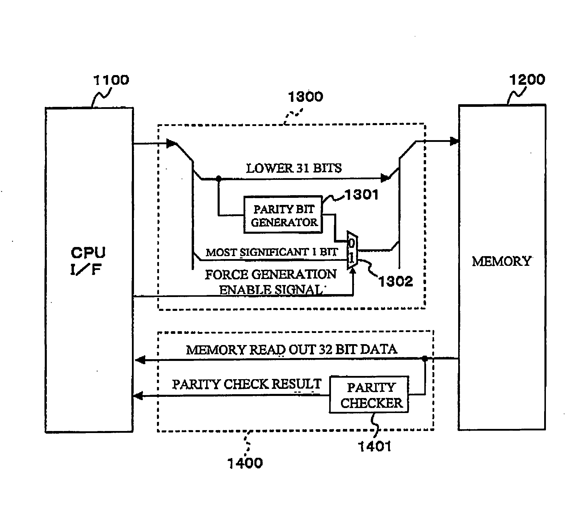
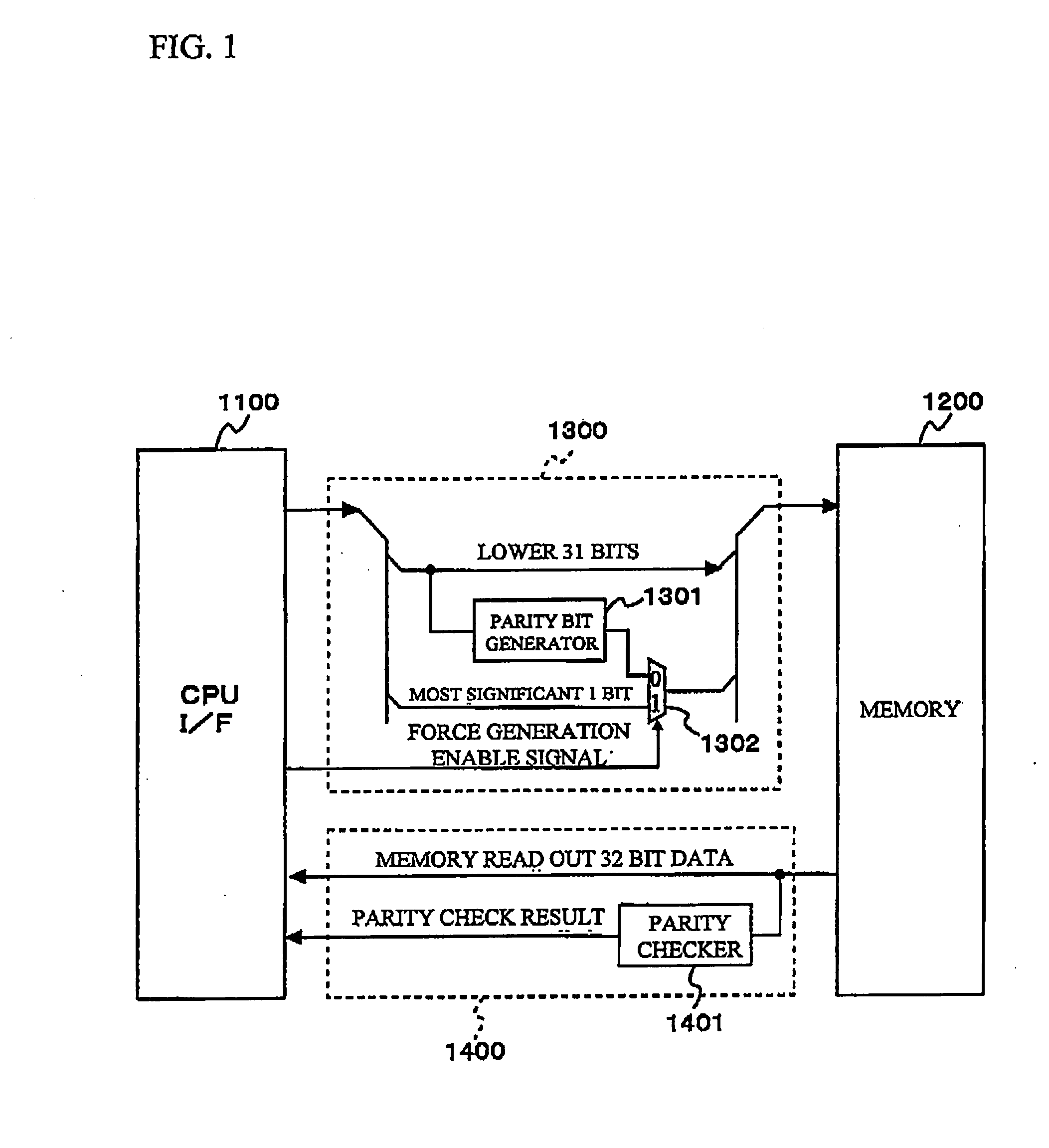
[0047]In reference with FIG. 1, a configuration of an error detector 1000 of a first embodiment of the present invention is described.

[0048]Bus lines that connect between a CPU I / F 1100 and a memory 1200 are connected with a parity bit summing unit 1300 which includes a parity bit generator 1301 (corresponds to an error detection data generator of the present invention) and a selector circuit 1302 (corresponds to a data switcher of the present invention).

[0049]The parity bit generator 1301 performs a parity operation on a data string which a CPU (corresponds to a diagnostic data transmitter and a failure diagnostic tool of the present invention) writes to the memory 1200, and appends a parity bit of the operation result to the data string. For example, when 32 bit data is written to the memory 1200, a parity operation on a data string composed of 31 bits is performed and a parity bit of the operation result is appended to the most significant bit (32nd bit) of the data string.

[0050]...

second embodiment

[0062]Next, a configuration of an in-vehicle gateway apparatus 1 with the abovementioned error detector 1000 installed is described.

[0063]In the in-vehicle gateway apparatus 1 shown in FIG. 3, a CPU bus 16 is connected with a CPU 2, a flash read only memory (ROM) 3, a universal asynchronous receiver transmitter (UART) 4, an interrupt control unit 6, a DMA controller 7, a CAN interface unit 8, a plurality of CANs 9 (while four CAN of CAN_0, CAN_1, CAN_2 and CAN_3 are shown in a second embodiment, the number of CANs is not limited to this), a bus interface unit 10, and the like. The bus interface unit 10 is connected with a search engine unit 11, a map memory 13, a sending buffer 14 and a receiving control unit 15. The search engine unit 11, the sending buffer 14 and the receiving control unit 15 are connected by data lines which input and output data from and to the CPU bus 16 via the bus interface unit 10. Between the search engine unit 11 and the sending buffer 14 and between the s...


PUM


Abstract

An error detector has a parity bit generator which generates error detection data for data strings sent from a CPU I / F to a memory, a parity checker which detects an error in the data strings output from the memory based on the error detection data, and a selector circuit which switchingly outputs the data from the parity bit generator and the data from a CPU which sends diagnostic data. While the selector circuit is switched to output the data from the CPU, based on the error detection data output from the selector circuit, the error detector conducts a failure diagnosis of error detection functions including at least one of the parity bit generator and the parity checker.

Description

INCORPORATION BY REFERENCE[0001]The disclosure of Japanese Patent Application No. 2006-293371 filed on Oct. 27, 2006 including the specification, drawings and abstract is incorporated herein by reference in its entirety.BACKGROUND OF THE INVENTION[0002]1. Field of the Invention[0003]The present invention relates to an error detector that detects data errors. More particularly, the present invention relates to an error detector suitable for installation on an in-vehicle gateway apparatus which relays data among a plurality of communication networks.[0004]2. Description of the Related Art[0005]In recent years, a plurality of ECUs such as an engine ECU, a door controlling ECU, an air-bag ECU, an audio ECU and a navigation ECU have been installed in a vehicle, as shown in FIG. 24. In order for these ECUs to make communication among a plurality of LANs that have different communication protocols and are in different communication speeds installed in a vehicle, a gateway apparatus which s...

Claims


Application Information

Patent Timeline
Patent Type & Authority Applications(United States)
IPC IPC(8): G06F11/00
CPCG06F11/10H04L1/0063H04L1/0045H04L1/243H04L1/244
Inventor NOUMI, KAORUNISHIHASHI, SUSUMUKATOU, TOMOYUKIISHIKAWA, YUKIOUMEZAKI, YASUYUKIEBESHU, HIDETAKAKOIDE, SHIGEOFUJISAWA, YUKIOSHIMAUCHI, HIROAKI
Owner RENESAS ELECTRONICS CORP
Why Eureka
Try Eureka