

Setter Used in Firing and Method for Firing of Formed Honeycomb Body Using the Setter
a technology of setter and honeycomb body, which is applied in the direction of lighting and heating apparatus, furnaces, charge manipulation, etc., can solve the problems of unsatisfactory shrinkage at the contact surface, generation of cell defects or lack of cells in some cases of the fired honeycomb body
Inactive Publication Date: 2008-06-19
NGK INSULATORS LTD
View PDF6 Cites 20 Cited by
- Summary
- Abstract
- Description
- Claims
- Application Information
AI Technical Summary
Problems solved by technology
This friction has caused a problem in that the formed honeycomb body after firing (the fired honeycomb body) has cracks at the contact surface or, even if no crack is generated, it is impossible to obtain a desired shrinkage at the contact surface and the formed honeycomb body after firing (the fired honeycomb body) is deformed.
When there is used a setter made of the same green body as
Method used
View moreImage
Smart ImageViewing Examples

Examples
 PUM
| Property | Measurement | Unit |
|---|---|---|
| Fraction | aaaaa | aaaaa |
| Fraction | aaaaa | aaaaa |
| Thickness | aaaaa | aaaaa |
Abstract
A support plate for use in firing which has a main component of the crystal phase after firing being the same as that of an article to be sintered, and has a surface roughness (Ra) of the surface to be contacted with the article to be fired of 8 to 50 μm. A firing method using the above support plate is free from the breaking or chipping of cells of a honeycomb fired article as a product and also is free from the breaking thereof during firing, the staining or cells, the cracking or deformation thereof, or the failure of reaction, which is caused by the mismatch in expansion-shrinkage behavior, and thus allows the prevention of the decrease of the yield in the production of a honeycomb fired article as a product.
Description
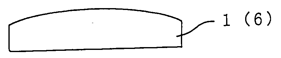
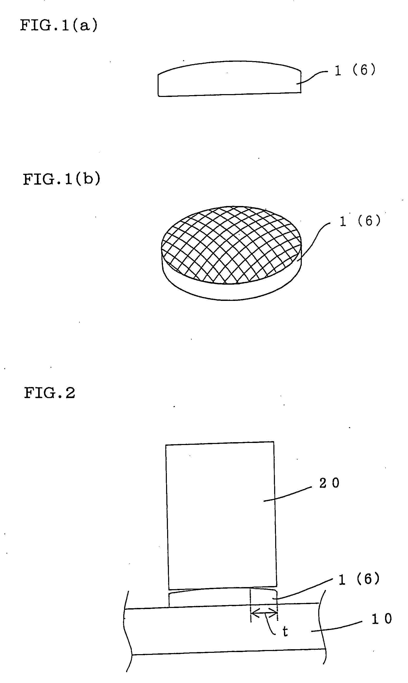
TECHNICAL FIELD[0001]The present invention relates to a setter used in firing and a method for firing of a formed honeycomb body using the setter.BACKGROUND ART[0002]In firing, for example, a formed honeycomb body (a ceramic honeycomb structure) which is a green body, it has been a general practice, for example, to place a setter 6 on a refractory slab 10 and mount thereon a formed honeycomb body 20, as shown in FIG. 2, and conduct firing in a tunnel furnace or a periodical kiln. In this case, however, the formed honeycomb body receives, in the firing step, firing shrinkage and thermal expansion and, in the contact surface between the formed ceramic body and the setter, a friction is generated by the difference in firing shrinkage and thermal expansion between the formed ceramic body and the setter. This friction has caused a problem in that the formed honeycomb body after firing (the fired honeycomb body) has cracks at the contact surface or, even if no crack is generated, it is im...
Claims
Login to View More Application Information
Patent Timeline
 IPC IPC(8): C04B35/64C04B35/195F27D3/12
CPCC04B35/195F27D5/0031C04B35/565C04B2235/3217C04B2235/3218C04B2235/3232C04B2235/3418C04B2235/3445C04B2235/349C04B2235/5409C04B2235/5436C04B2235/77C04B2235/9623C04B2235/963F27D3/12C04B35/478
InventorNOGUCHI, YASUSHISUENOBU, HIROYUKINAKAMURA, TOMOOWATANABE, TAKEHIKO
OwnerNGK INSULATORS LTD