Auto-drive apparatus

a technology for auto-driving and apparatus, which is applied in the direction of process and machine control, instruments, navigation instruments, etc., can solve the problems of insufficient travel controllers, insufficient occupancy alone of running vehicles, and the inability of vehicles to start auto-driving functions without a destination setting

Inactive Publication Date: 2018-08-09
DENSO CORP
View PDF30 Cites 20 Cited by
  • Summary
  • Abstract
  • Description
  • Claims
  • Application Information

AI Technical Summary

Benefits of technology

[0014]According to the above configuration, the auto-drive processor engages the auto-drive function of the subject vehicle to automatically drive the subject vehicle to a road near or proximate to the current location of the subject vehicle when a driver's seat occupant/user is present in the subject vehicle and the condition determiner determines that a start

Problems solved by technology

However, when the vehicle described in patent document 1 is not currently traveling on the road, the vehicle cannot start the auto-drive function without a destination setting.
In other words, occupancy alone of a running vehicle not currently traveling along a road known to the vehicle and/or travel controller is not sufficient for starting the auto-drive function of the vehicle, because the travel controller in patent document 1 relies on either identifying a current road of travel

Method used


Image

  • Auto-drive apparatus
  • Auto-drive apparatus
  • Auto-drive apparatus

Examples


first embodiment

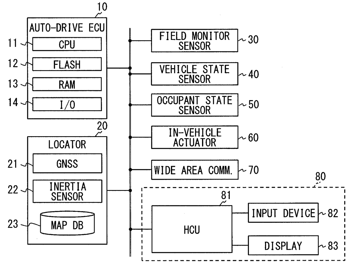
[0031]With reference to FIG. 1, the vehicle control system of the present embodiment may include an auto-drive ECU 10, a locator 20, a field monitor sensor 30, a vehicle state sensor 40, an occupant state sensor 50, an in-vehicle actuator 60, a wide area communicator 70, and an HMI system 80. ECU is an abbreviation for an Electronic Control Unit, that may be an electronic control circuit installed in a vehicle, and HMI is an abbreviation for a Human Machine Interface.

[0032]Each of the locator 20, the field monitor sensor 30, the vehicle state sensor 40, the occupant state sensor 50, the in-vehicle actuator 60, the wide area communicator 70, and the HMI system 80 is communicatively connected with the auto-drive ECU 10 via a communication network such as a Local Area Network or “LAN” within the subject vehicle. The vehicle having the vehicle control system may also be designated as a “subject vehicle” and a person using the subject may be designated as a “user.” An “occupant” indicate...

second embodiment

[0109]The vehicle control system concerning the second embodiment of the present disclosure is described with reference to the drawings. The difference between the first embodiment and the second embodiment is the operation of the auto-drive ECU 10 when the auto-drive start condition is satisfied with no destination setting. Hereafter, the function and operation realized by the auto-drive ECU 10 in the second embodiment are described. The same numerals are assigned to the same components as the first embodiment, and the description of those components is not repeated. When only a part of the configuration is described, the rest of the configuration is borrowed from the first embodiment.

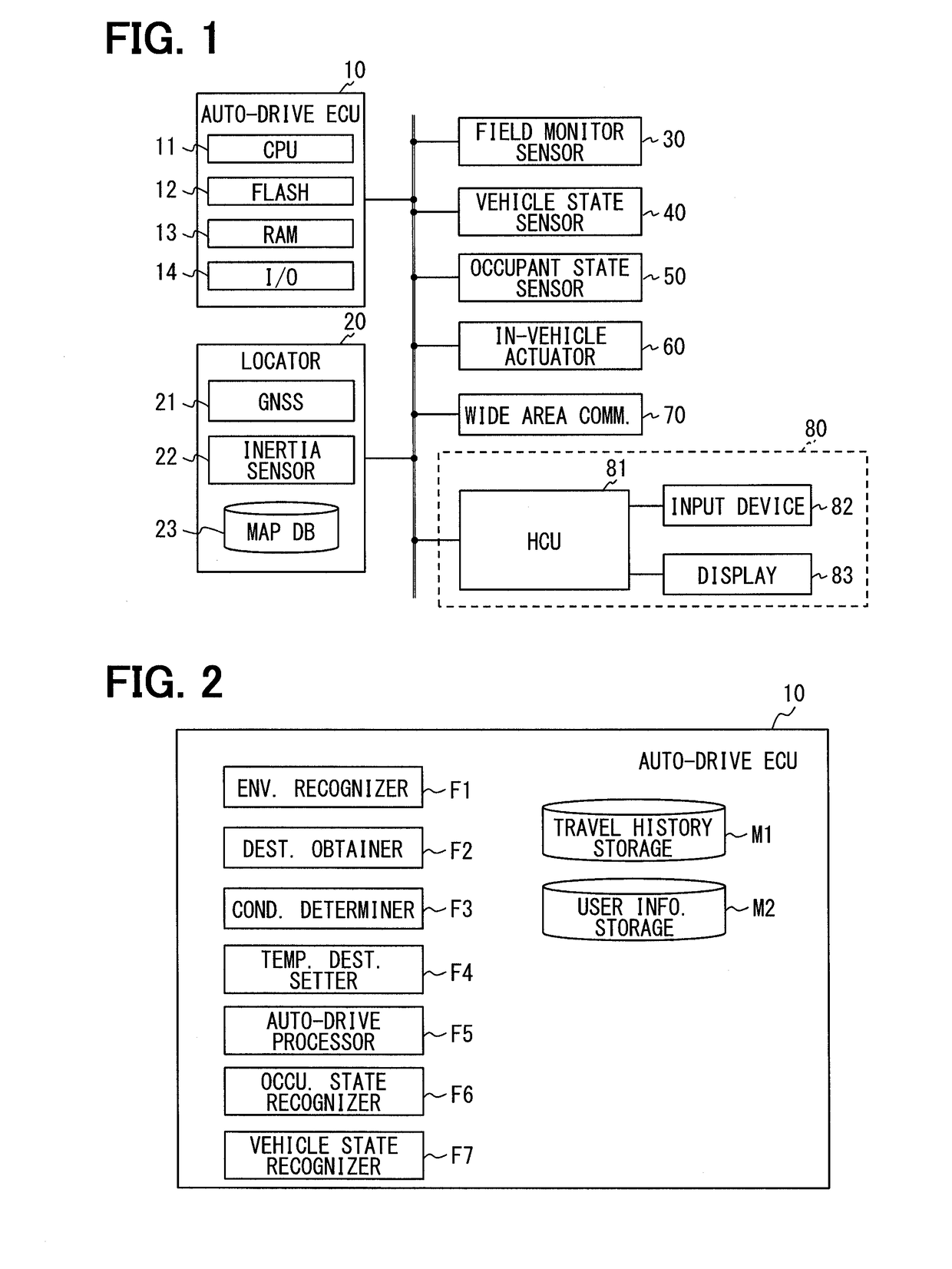
[0110]The auto-drive ECU 10 in the present embodiment is provided with the environment recognizer F1, the destination obtainer F2, the condition determiner F3, the auto-drive processor F5, the occupant state recognizer F6, the vehicle state recognizer F7, a temporary travel direction setter F8, the tr...

third embodiment

[Third Embodiment]

[0129]The user may use the vehicle compartment of the auto-driving vehicle as a work space, a movie theater, a room for taking a nap, or the like. As a result, it is naturally assumed that a vehicle capable of performing auto-drive may be used for the purposes other than travel. However, when the user uses the subject vehicle for purposes other than travel, such as a sleep or the like, no destination is set. Therefore, in other words, even when no destination is set for the auto-drive of the subject vehicle, simply continuing an auto-drive of the subject vehicle may be foreseen as a need of the user.

[0130]The vehicle control system concerning the third embodiment of the present disclosure is created and configured for satisfying such a need as one of the travel purposes. The vehicle control system of the third embodiment is provided with the same configuration as the vehicle control system of the first and second embodiment described above. The difference between t...


PUM


Abstract

An auto-drive apparatus includes a condition determiner for determining whether an auto-drive start condition of a vehicle is satisfied based on a detection of a boarding action by a user. When no destination has been set at a time when the auto-drive start condition is satisfied, a temporary destination setter sets a temporary destination, which is a position on a nearby road that is reachable in a minimum travel time or via a shortest travel distance from a current vehicle position. An auto-drive processor plans a route to the temporary destination and starts the auto-drive of the vehicle toward the temporary destination.

Description

CROSS REFERENCE TO RELATED APPLICATION[0001]The present application is based on and claims the benefit of priority of Japanese Patent Application No. 2017-019664, filed on Feb. 6, 2017, the disclosure of which is incorporated herein by reference.TECHNICAL FIELD[0002]The present disclosure generally relates to an auto-drive apparatus that automatically drives, or controls a travel of, a subject vehicle to a preset destination.BACKGROUND INFORMATION[0003]In recent years, as disclosed in a patent document 1, i.e. Japanese Application Publication No. 2012-216069, an occupant in a vehicle's driver's seat (hereinafter referred to as “a driver seat occupant”) can rely on an autopilot / auto-drive function that automatically drives the vehicle and controls vehicle travel toward a preset destination.[0004]As described in patent document 1, in cases where the driver seat occupant turns ON the auto-drive function where no destination is set, the vehicle is controlled to continue automatically dr...

Claims


Application Information

Patent Timeline
IPC IPC(8): G05D1/00G05D1/02
CPCG05D1/0088G05D1/0214G05D1/0061G05D1/0274G05D2201/0213G05D1/027G05D1/0278G05D1/0055G01C21/3407G01C21/3605B60W50/00B60W2540/26B60W2420/40B60W60/0051B60W2540/221B60W2552/05B60W40/08B60W50/082B60W2556/10B60W2540/225B60W60/0016
Inventor TANAHASHI, AKIHITOITO, TOSHIYUKINAGANUMA, TAKAHIRO
Owner DENSO CORP
Why Eureka
Try Eureka