Image processing device, imaging system and imaging apparatus including the same, and image processing method

a technology of image processing and imaging system, applied in image enhancement, color signal processing circuit, instruments, etc., can solve the problems of unnatural motion in the shape of the photographic subject that appears, loss of a portion of the foreground shape, and loss of two foreground shapes, so as to reduce the amount of parallax correction and prevent unnatural motion

Active Publication Date: 2016-08-11
PANASONIC INTELLECTUAL PROPERTY MANAGEMENT CO LTD
View PDF5 Cites 20 Cited by
  • Summary
  • Abstract
  • Description
  • Claims
  • Application Information

AI Technical Summary

Benefits of technology

[0012]An object of the present disclosure is that, in panoramic composite image, a boundary of an area of each captured image that is composed is suppressed from being unnaturally conspicuous while an area of a captured image that is a reference is suitably displayed. Another object of the present disclosure is to prevent an unnatural motion from occurring in a shape of a photographic subject that appears in a display image, without giving a viewer a feeling that something is wrong when a panoramic composite image is displayed as a moving image in a case where parallax correction that deforms an image according to parallax is performed on multiple captured images for composition.
[0023]According to the present disclosure, in a panoramic composite image, a boundary of an area of each captured image that is composed can be suppressed from being unnaturally conspicuous while an area of a captured image that is a reference is suitably displayed. Furthermore, according to the present disclosure, because an amount of change over time by which an amount of parallax correction is changed is limited by a filter, even if a change in which two captured images are greatly different in parallax from each other occurs, the amount of parallax correction is set to be changed in stages instead of being suddenly changed. Because of this, image deformation that is performed in a parallax corrector based on an amount of parallax correction is reduced. Thus, the image deformation is performed in stages. For this reason, when a panoramic composite image is displayed as a moving image, an unnatural motion can be prevented from occurring in the shape of the photographic subject that appears in an image, without giving a viewer a feeling that something is wrong.

Problems solved by technology

On the other hand, when photographic subjects that are positioned at greatly different distances from the camera are present, that is, a photographic subject in the background and a photographic subject in the foreground are present in the overlapping portions of the image capture areas of the two cameras, a defect occurs in that a state where deviation takes place in a positional relationship between a shape of the photographic subject in the background and a shape of the photographic subject in the foreground, that is, so-called parallax occurs between captured images that are acquired by two cameras, and thus, in a composite image, the same two foreground shapes appear in an overlapping manner or one portion of the foreground shape is lost.
As a result, a sudden change in the image occurs between the frames, and when the composite image is displayed as a moving image, an unnatural motion occurs in the shape of the photographic subject that appears in the image.
However, an amount of computation in the stitching processing is large, and in a case where information on a future frame is necessary, it is difficult to perform real time processing that, in real time, outputs the image which is captured in the camera while performing the stitching processing.
Additionally, when the stitching processing is performed on the captured images (the composed images) that are acquired by the multiple cameras in which imaging conditions are set individually, without any change, a boundary of an area of each of the captured images in the composite image is made to be unnaturally conspicuous by a difference in brightness or shade between the captured images.
However, a case can occur in which the exposure or the white balance is not suitably set in the camera that acquires the captured image (for example, a captured image that has high importance, which a user is likely to pay attention to) that is a reference, and in which an imaging target is not suitably displayed (for example, blown-out highlight, blocked-up shadows, or the like occur).

Method used


Image

  • Image processing device, imaging system and imaging apparatus including the same, and image processing method
  • Image processing device, imaging system and imaging apparatus including the same, and image processing method
  • Image processing device, imaging system and imaging apparatus including the same, and image processing method

Examples


first exemplary embodiment

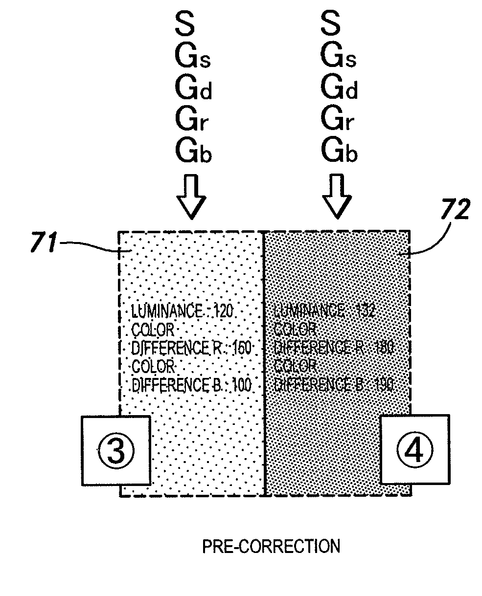
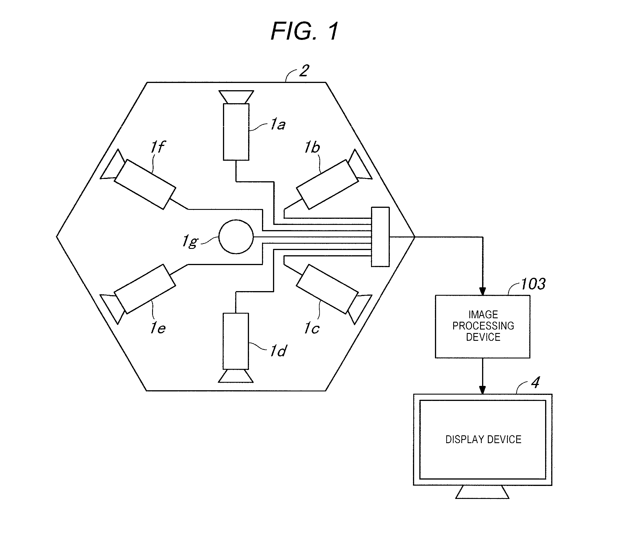
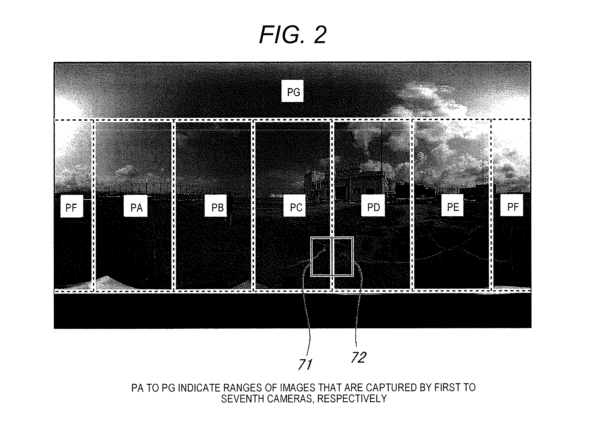
[0045]FIG. 1 is a diagram illustrating an entire configuration of an image processing system according to a first exemplary embodiment. FIG. 2 is an explanatory diagram illustrating a composite image that is generated in image processing device 3 which is illustrated in FIG. 1 and is displayed on display device 4.

[0046]The present image processing system, as illustrated in FIG. 1, includes camera unit 2 having first to seventh cameras 1a to 1g, image processing device 3, and display device 4.

[0047]Cameras 1a to 1g each have a wide angle of view (for example, 120 degrees). First to sixth cameras 1a to 1f are arranged at equal distances in a circumferential direction in such a manner that an optical axis is in a radial pattern in an approximately horizontal direction. Seventh camera 1g is arranged in such a manner that the optical axis is in approximately vertical direction. Cameras 1a to 1g are arranged in such a manner that portions of image capture areas of two adjacent cameras amo...

second exemplary embodiment

[0078]Next, a second exemplary embodiment is described. FIG. 7 is an explanatory diagram illustrating camera unit 21 according to the second exemplary embodiment. FIG. 8 is a functional block diagram illustrating a schematic configuration of image processing device 23 according to the second exemplary embodiment. What is particularly not mentioned hereinafter is the same as in the exemplary embodiment described above.

[0079]According to the first exemplary embodiment, the amount of parallax correction is set to be calculated from the captured images that are acquired by cameras 1a to 1g, but according to the second exemplary embodiment, as illustrated in FIG. 7, depth sensor (distance detection devices) 22a to 22f are provided in camera unit 21 and the amount of parallax correction is set to be calculated based on results of detection by depth sensors 22a to 22f.

[0080]Depth sensors 22a to 22f are distance image sensors that detects a depth of an image, that is, a distance to a photo...

third exemplary embodiment

[0082]Next, a third exemplary embodiment is described. FIG. 9 is a diagram illustrating an entire configuration of an image processing system according to a third exemplary embodiment. FIG. 10 is a functional block diagram illustrating a schematic configuration of PC 31 that is illustrated in FIG. 9. FIGS. 11A to 11C are explanatory diagrams illustrating a screen that is displayed on display device 4 that is illustrated in FIG. 9. What is particularly not mentioned hereinafter is the same as in the embodiment described above.

[0083]The image processing system according to the third exemplary embodiment, as illustrated in FIG. 9, includes camera unit 2, PC 31 (an information processing apparatus), display device 4, and a mouse (an operation input device) 32.

[0084]As illustrated in FIG. 10, PC 31 includes image accumulator 41, first image processor 42, second image processor 43, image abnormality detector 44, correction area setter 45, amount-of-parallax-correction setter 46, and input...


PUM


Abstract

An image processing device includes a reference camera determiner that determines one among the multiple cameras, as a reference camera; an imaging condition acquisition unit that acquires imaging conditions relating to exposure and white balance which are set in the reference camera; an imaging condition setter that sends a command to set the imaging conditions relating to the exposure and the white balance, based on the imaging conditions in the reference camera, to cameras other than the reference camera; and an image composition unit that performs image composition processing on the multiple captured images that are acquired from the multiple cameras and that outputs the panoramic composite image. Thus, a boundary of an area of each composed image in the panoramic composite image that results from the composition is suppressed from being unnaturally conspicuous, and the captured image that is a reference is suitably displayed.

Description

BACKGROUND OF THE INVENTION[0001]1. Field of the Invention[0002]The present disclosure relates to an image processing device that performs image composition processing on multiple captured images and outputs a composite image, an imaging system and an imaging apparatus that include the image processing device, and an image processing method.[0003]2. Description of the Related Art[0004]A wide angle image that cannot be obtained with one camera can be generated in a seamless state, by performing so-called stitching processing that composes images that are captured by multiple cameras and generates one composite image (a panoramic image). In this stitching processing, two adjacent cameras are arranged in such a manner that portions of image capture areas overlap, and images are composed by superimposing image areas of boundary portions that correspond to overlapping portions of image capture areas of two cameras, on each other, or by suitably performing trimming.[0005]On the other hand...

Claims


Application Information

Patent Timeline
Patent Type & Authority Applications(United States)
IPC IPC(8): H04N5/232H04N5/265H04N5/235G06T5/00G06K9/46G06T7/40G06T7/00G06K9/62H04N5/247H04N9/73
CPCH04N5/23238G06T2207/30168H04N5/265H04N5/235H04N9/73G06K9/4661G06K9/4652G06T7/408G06K9/4604G06T7/0085G06K9/6215G06T5/006G06T2207/20221G06T2200/32G06T2207/20024H04N5/247H04N1/3876G06V10/16H04N23/698H04N23/70H04N23/90H04N23/88
Inventor KUWADA, JUNYAOGINO, RYOJIHIROTA, RYONISHIYAMA, AKIO
Owner PANASONIC INTELLECTUAL PROPERTY MANAGEMENT CO LTD
Why Eureka
Try Eureka