Aircraft safety system

a safety system and aircraft technology, applied in the field of aircraft safety systems, can solve the problems of unusable wing release mechanisms, difficult installation and use of wing release mechanisms, and difficulty in parachuting deploymen

Active Publication Date: 2008-06-19
MANFREDI DARIO P +1
View PDF15 Cites 23 Cited by
  • Summary
  • Abstract
  • Description
  • Claims
  • Application Information

AI Technical Summary

Benefits of technology

[0004]An object of the present invention is to provide an aircraft safety sys...

Problems solved by technology

Usually, the wing-release mechanisms are not easy to install and may not be easy to use.
This, in turn, renders the wing release mechanisms unusable in ...

Method used


Image

  • Aircraft safety system
  • Aircraft safety system
  • Aircraft safety system

Examples


Embodiment Construction

[0019]Embodiments of the present invention provide a system for enabling a safe landing of an aircraft during an in-flight emergency. In the description of the present invention, numerous specific details are provided, such as examples of components and / or mechanisms, to provide a thorough understanding of the various embodiments of the present invention. One skilled in the relevant art will recognize, however, that an embodiment of the present invention can be practiced without one or more of the specific details, or with other apparatus, systems, assemblies, methods, components, materials, parts, and / or the like. In other instances, well-known structures, materials, or operations are not specifically shown or described in detail to avoid obscuring aspects of embodiments of the present invention.

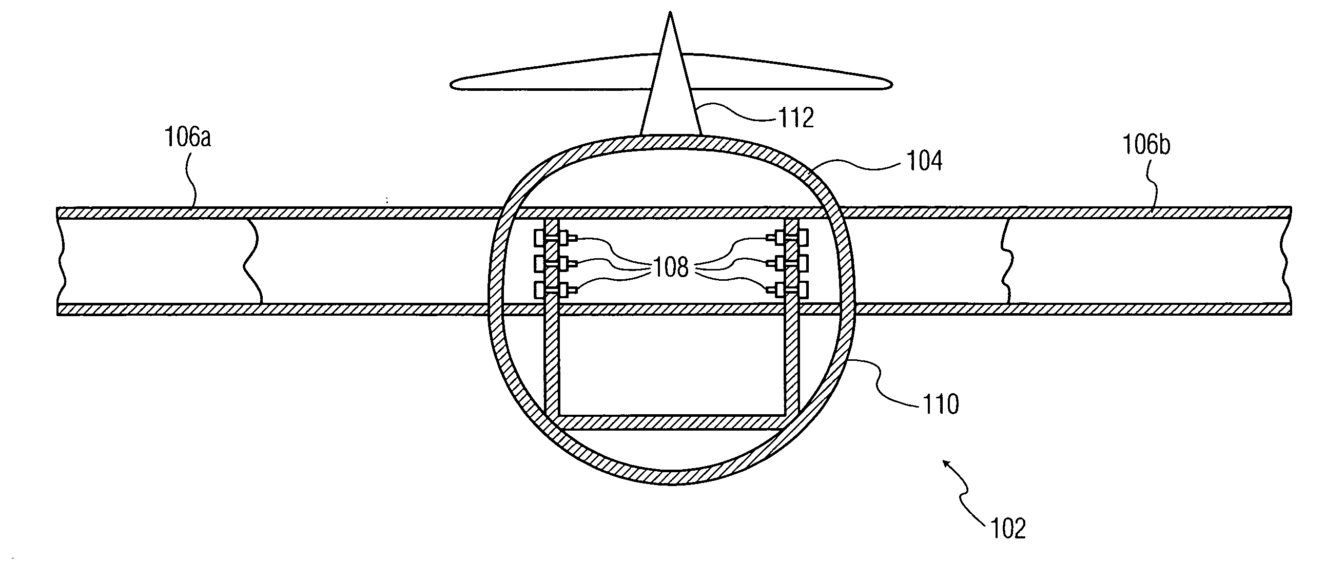
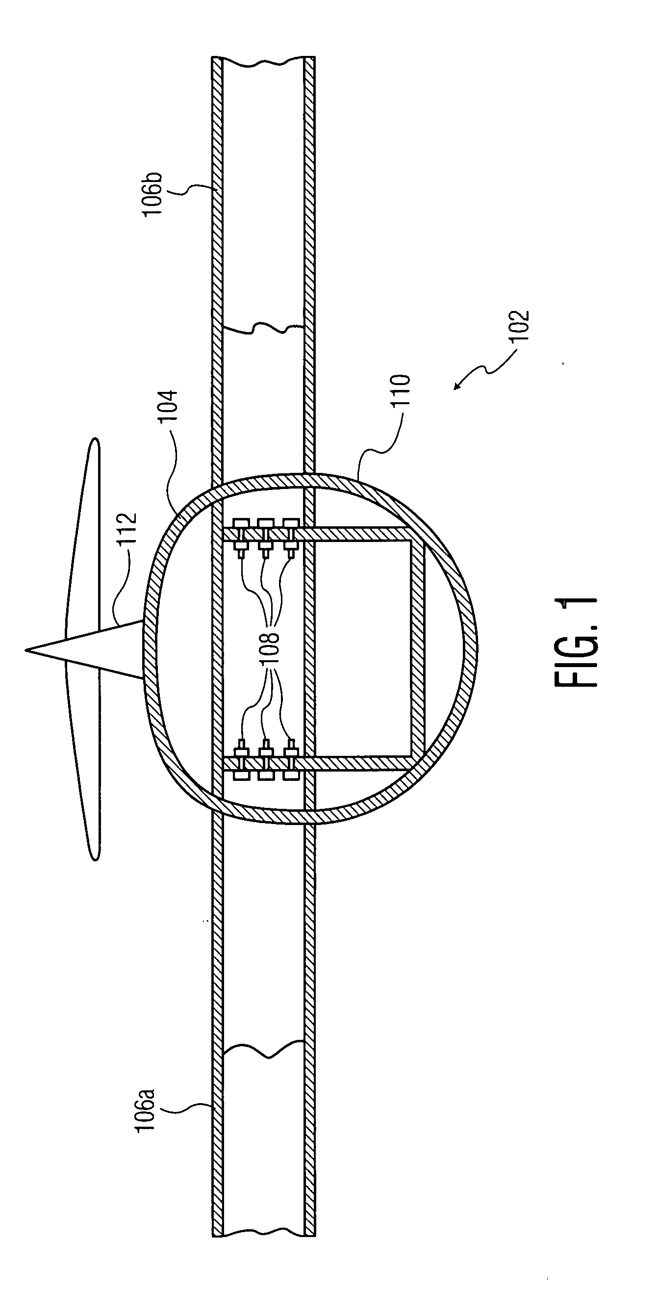
[0020]FIG. 1 illustrates a partial cross-sectional view of an aircraft 102, wherein embodiments of the present invention may be practiced. Aircraft 102 includes a fuselage 104 and a plurali...


PUM


Abstract

A system for enabling the safe landing of an aircraft during an in-flight emergency is provided. The system includes a plurality of onboard devices for releasably securing a plurality of wings to a fuselage, and a non-electric module for activating said onboard devices. Said onboard devices are released to separate said wings from the fuselage.

Description

BACKGROUND OF THE INVENTION[0001]The present invention relates, in general, to the field of aviation. More specifically, it relates to a system that enables the safe landing of an aircraft in case of an in-flight emergency.[0002]In the eventuality of an in-flight emergency, an aircraft may be required to perform emergency landing procedures. In order to facilitate safe emergency landing procedures, the aircraft is equipped with various aircraft safety systems. These aircraft safety systems may deploy safety devices, such as parachutes, drog chutes, rocket members, and airbags. For example, the parachutes help to reduce the downward speed of the fall of the aircraft during the in-flight emergency. The ‘Drog chutes’ help in reducing the forward speed of the aircraft. The ‘rocket members’ may be used for reducing the downward speed of the fall of the aircraft, the forward speed of the aircraft, or both, depending on their alignment with the aircraft. The ‘airbags’ help in reducing the ...

Claims


Application Information

Patent Timeline
IPC IPC(8): B64C1/32F42B3/00B64C1/00B64D25/00B64D17/00
CPCB64D25/00B64D25/12F42B15/36F41H11/02F42B3/006B64D2201/00
Inventor MANFREDI, DARIO P.GIARRAFFA, SAVIA N.
Owner MANFREDI DARIO P
Why Eureka
Try Eureka