Solenoid Actuator Motion Detection

a solenoid actuator and motion detection technology, applied in the field of solenoid actuator motion detection instrumentation, can solve the problems of high inductance solenoid valve, inability to use all applications of system for detecting solenoid actuator motion, and control of solenoid valves by pulse width modulation (pwm)

Inactive Publication Date: 2008-06-19
CONTINENTAL AUTOMOTIVE SYST INC
View PDF7 Cites 18 Cited by
  • Summary
  • Abstract
  • Description
  • Claims
  • Application Information

AI Technical Summary

Benefits of technology

[0009]One aspect of the invention provides a method of determining change in actuator position that includes determining a slope of the inductor current with time and determining whether the slope exceeds a first predetermined slope for a first predetermined time, determining whether the slope is less than a second predetermined slope for a second predetermined time when the slope exceeds the first predetermined slope for the first predetermined time, and determining whether the slope exceeds a third predetermined slope for a third predetermined time when the slope is less than the second predetermined slope for the second predetermined time. The method further includes determining the change in actuator position when the slope exceeds the third predetermined slope for the third predetermined time.

Problems solved by technology

Unfortunately, not all solenoid valves exhibit the current profile of FIG. 1A.
High inductance solenoid valves are not desirable in all applications, so the present systems for detecting solenoid actuator motion cannot be used for all applications.
Another problem for the present systems is solenoid valves controlled by Pulse Width Modulation (PWM) circuitry.

Method used


Image

  • Solenoid Actuator Motion Detection
  • Solenoid Actuator Motion Detection
  • Solenoid Actuator Motion Detection

Examples


Embodiment Construction

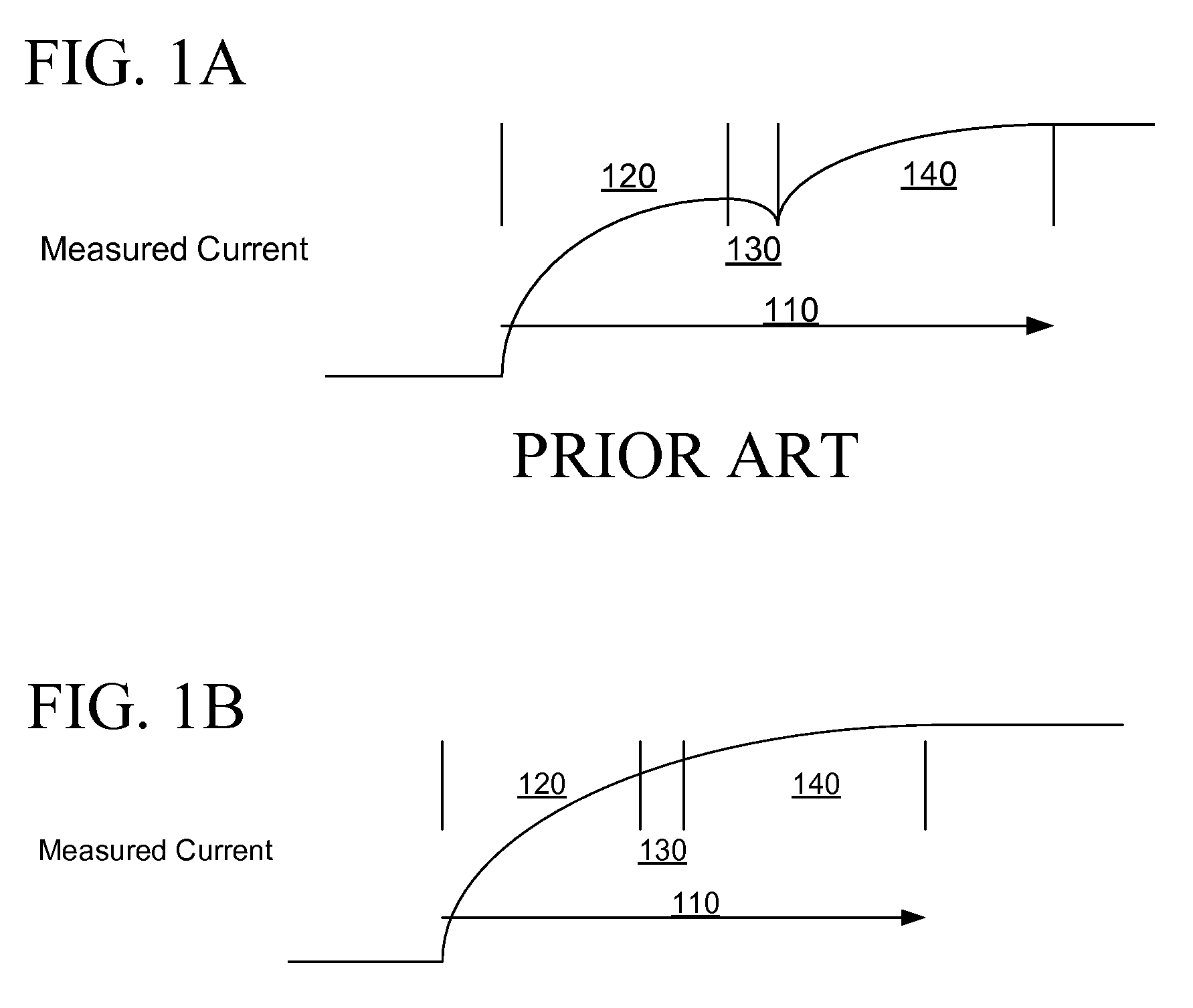
[0024]Use of the disclosures herein allows determination of actuator position changes for low impedance solenoid valves by determining changes in current slope instead of negative current slopes.

[0025]FIG. 3 illustrates the current flow through a sense resistor in communication with a low inductance solenoid valve in accordance with one aspect of the invention. Current applied to a ferrous core of a solenoid valve increases during a first portion 120 of the curve, increases at a lower, non-zero, positive rate during a second portion 130 of the curve, and a third rate during a third portion 140 of the curve with respect to time 115. Each current sample is identified as sample 160.

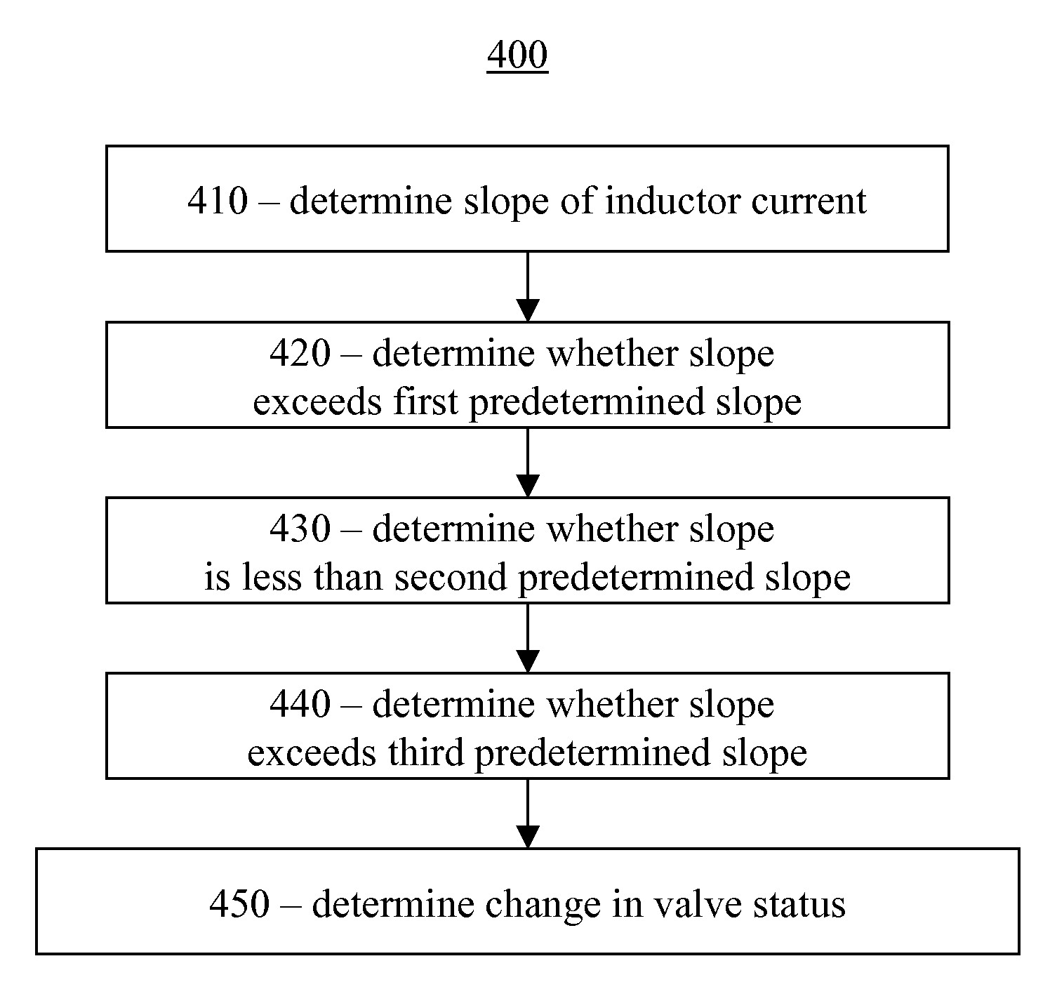
[0026]FIG. 4 illustrates one embodiment of a method 400 for determining change in actuator states in accordance with one aspect of the invention.

[0027]Method 400 begins by determining a slope of the inductor current with time at block 410. The slope is determined by the difference between sequential samples ...


PUM


Abstract

A method of determining change in actuator position includes determining a slope of the inductor current with time and determining whether the slope exceeds a first predetermined slope for a first predetermined time, determining whether the slope is less than a second predetermined slope for a second predetermined time when the slope exceeds the first predetermined slope for the first predetermined time, and determining whether the slope exceeds a third predetermined slope for a third predetermined time when the slope is less than the second predetermined slope for the second predetermined time. The method further includes determining the change in actuator position when the slope exceeds the third predetermined slope for the third predetermined time.

Description

TECHNICAL FIELD OF THE INVENTION[0001]The present invention relates generally to actuator instrumentation and more particularly to solenoid actuator motion detection instrumentation.BACKGROUND OF THE INVENTION[0002]Solenoid actuators, such as solenoid valves, are common in many applications. These applications include automobiles, including but not limited to, the power train. In use, it is often advantageous to know whether the actuator is open or closed, or more precisely whether the actuator position (i.e. open or closed) has changed. Knowledge of the actuator position allows for an error check to make sure that an actuator that is supposed to open is actually open and a actuator that is supposed to be closed is actually closed.[0003]A solenoid actuator includes a solenoid wrapped around a solenoid core, which is attached to a valve, gear, or other device to be moved. When a current is applied to the solenoid, the magnetic field from the solenoid produces a force on the solenoid ...

Claims


Application Information

Patent Timeline
Patent Type & Authority Applications(United States)
IPC IPC(8): G01R27/26G01R19/00G01R31/72
CPCG01R31/06H01F2007/185H01F7/1844Y10T137/0318G01R31/72
Inventor ROBER, STEPHEN
Owner CONTINENTAL AUTOMOTIVE SYST INC
Why Eureka
Try Eureka