Automatic drum rotation control concrete transit mixer truck

a technology of automatic drum rotation and concrete, which is applied in the direction of control apparatus, clay preparation apparatus, chemistry apparatus and processes, etc., can solve the problems of expensive repair of drum and fins, wear of fins and interior linings, and need replacemen

Active Publication Date: 2008-06-19
SCHWING AMERICA
View PDF7 Cites 40 Cited by
  • Summary
  • Abstract
  • Description
  • Claims
  • Application Information

AI Technical Summary

Benefits of technology

[0009]A control system for transit mixer truck automatically controls the drum drive system based upon sensed vehicle speed. When the speed of the transit mixer truck exceeds a threshold, the control system causes the drum drive system to rotate the drum at a constant speed.

Problems solved by technology

Over time, the fins and the interior lining of the drum will be worn to an extent that they require replacement.
The replacement of the drum and the fins is an expensive repair.
This can yield significant benefits in maintenance costs for the truck.
Despite the benefits of a constant drum speed feature, it has not achieved widespread usage, even among businesses owning the trucks with the constant drum speed feature.

Method used


Image

  • Automatic drum rotation control concrete transit mixer truck
  • Automatic drum rotation control concrete transit mixer truck
  • Automatic drum rotation control concrete transit mixer truck

Examples


Embodiment Construction

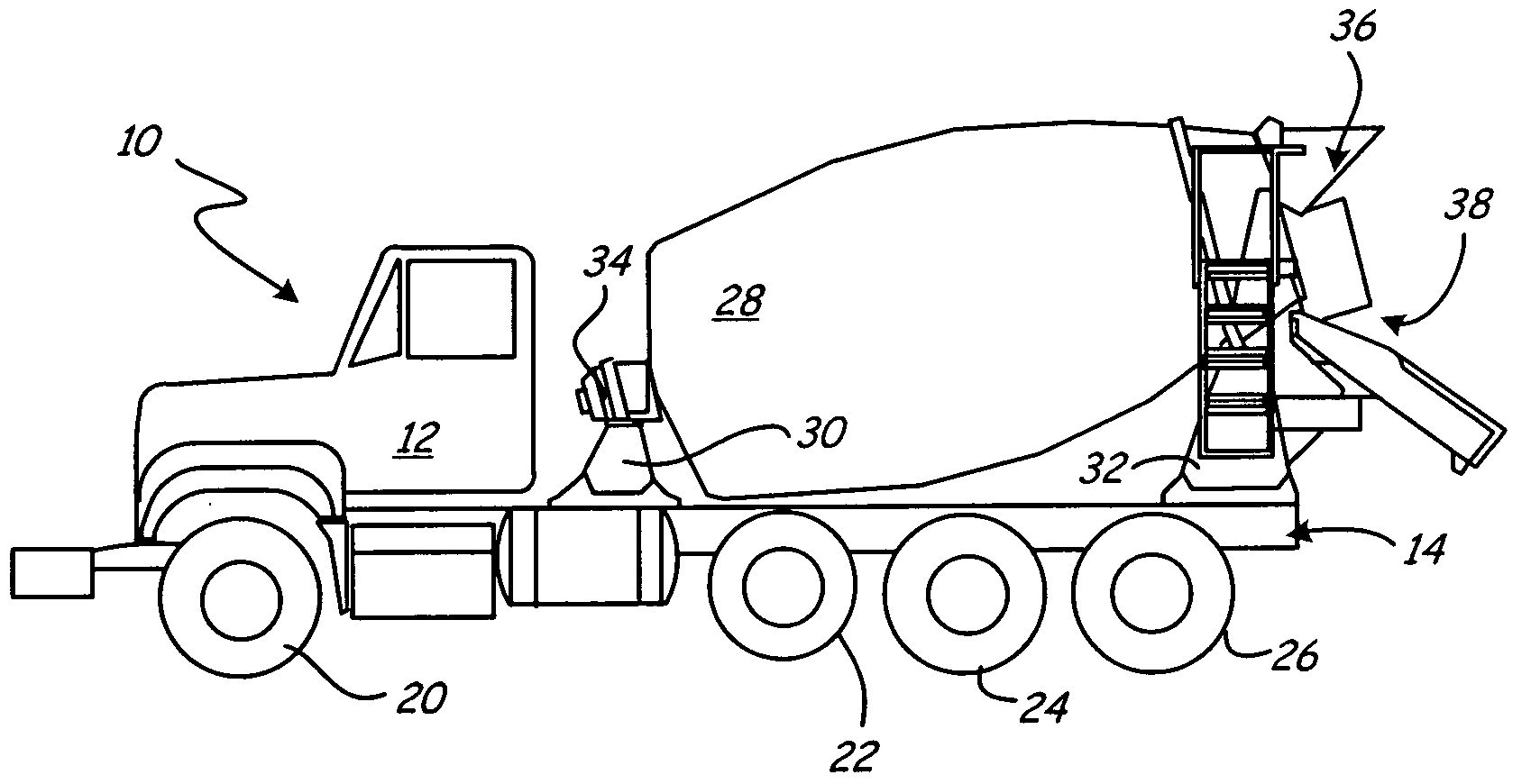
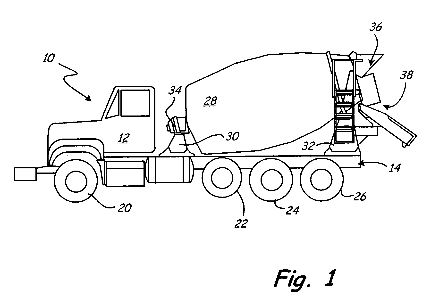
[0012]FIG. 1 is a side view of concrete mixing truck 10, which includes cab 12, chassis 14, wheels 20, 22, 24 and 26, drum 28, front pedestal 30, rear pedestal 32, hydraulic drive 34, discharge opening 36, and chute 38. Mixer drum 28 holds and mixes concrete, and is supported by chassis 14 between front pedestal 30 and rear pedestal 32. Rear pedestal 30 has a greater height than front pedestal 32, so that the rear of drum 28 is elevated.

[0013]Hydraulic drive 34 rotates drum 28 in a charge direction to mix the concrete while truck 10 is traveling to the work site. When truck 10 is in position at the work site to deliver the concrete, the driver causes hydraulic drive 34 to reverse the rotation of drum 28 so that it rotates in the discharge direction. As the drum rotates, the fins within drum 28 move the concrete toward discharge opening 36. The concrete is delivered out of drum 28 through discharge opening 36 and down chute 38.

[0014]Hydraulic drive 34 is driven by a power take-off fr...


PUM

PropertyMeasurementUnit
speedaaaaaaaaaa
constant drum speedaaaaaaaaaa
drum speedaaaaaaaaaa

Abstract

A concrete transit mixer truck includes a control system that automatically controls rotation of the mixer drum at a constant drum speed when the mixer truck is traveling. When sensed speed of the truck exceeds a threshold, the control system automatically causes a hydraulic system to rotate the drum at a constant speed, regardless of the truck engine speed.

Description

BACKGROUND OF THE INVENTION[0001]The present invention relates to concrete transit mixing trucks. In particular, the invention relates to a control system for controlling rotation of the drum of the mixer truck while the truck is in motion.[0002]Concrete transit mixer trucks are used to transport concrete to a worksite while mixing or agitating the payload of cement, aggregate, sand and water. Fins within the drum mix the payload as the drum rotates.[0003]As the concrete constituents are initially loaded into the drum, and as the truck moves to the worksite, the drum is rotated in a first or charge direction, so that the payload tends to move away from discharge opening of the drum. At the worksite, the rotation of the drum is reversed so that it rotates in a second or discharge direction. The fins move the payload toward the discharge opening. A chute attached below the discharge opening delivers the concrete from the drum to the worksite.[0004]The drum is rotated by a hydraulic dr...

Claims


Application Information

Patent Timeline
Patent Type & Authority Applications(United States)
IPC IPC(8): B28C5/42B28C7/02
CPCB28C5/422
Inventor SCHUMACHER, CHARLES P.KRASNY, ALEXANDERWORTHMANN, HEINZ ULRICHDURAND, ROBERT BENJAMINQUIST, CARL PHILLIP
Owner SCHWING AMERICA
Why Eureka
Try Eureka