
Sliding-type mechanism and portable electronic device using the same

a technology of sliding-type mechanism and electronic device, which is applied in the direction of mechanical equipment, substation equipment, wound springs, etc., can solve the problems of insufficient driving force of torsion springs, user discomfort, and complex manufacturing/assembly of conventional sliding-type mechanisms

Inactive Publication Date: 2008-06-19
FIH (HONG KONG) LTD
View PDF1 Cites 57 Cited by
  • Summary
  • Abstract
  • Description
  • Claims
  • Application Information

AI Technical Summary

Benefits of technology

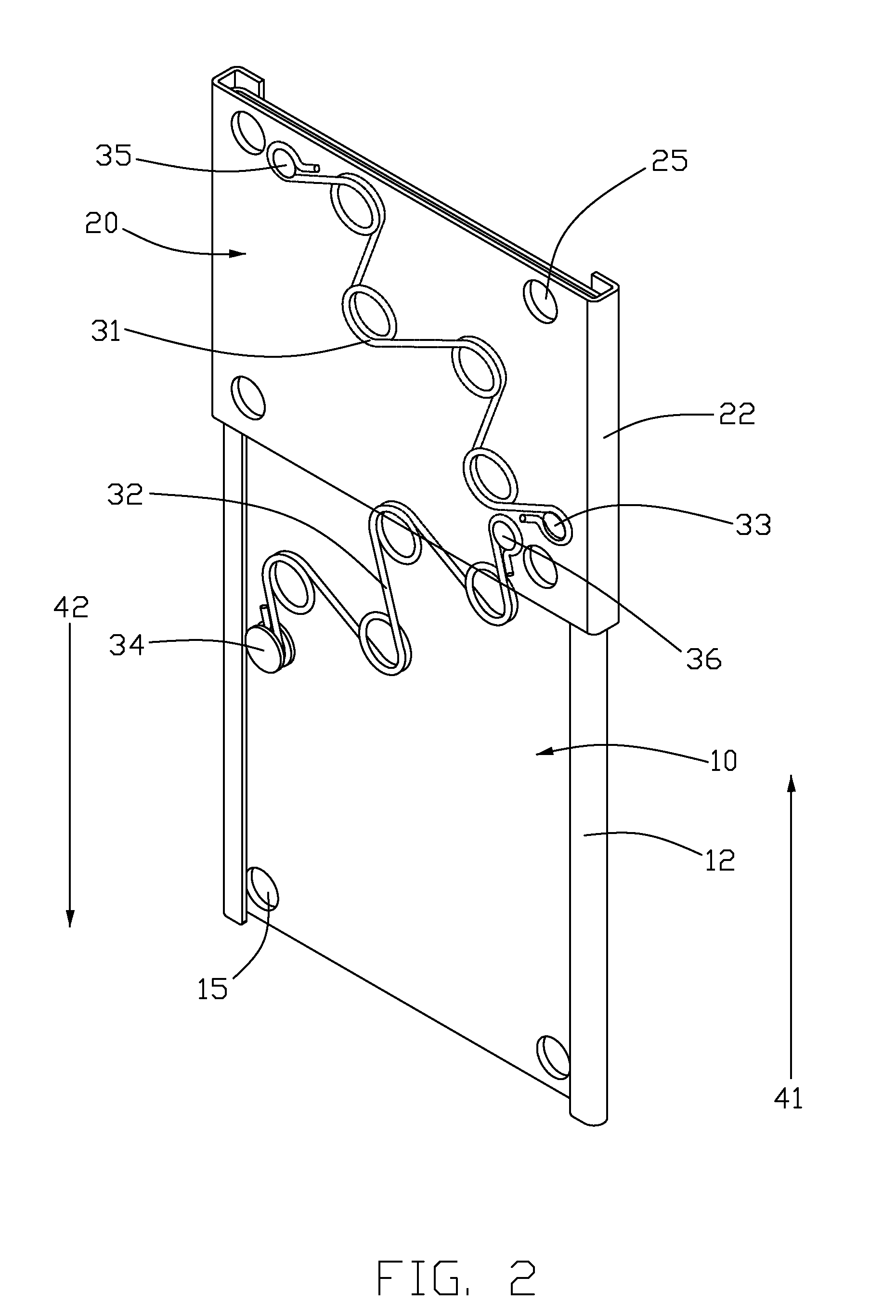
[0013]In yet another aspect, the present invention relates to a sliding-type mechanism for providing a force to drive a first plate engaged with a second plate to slidably move back and forth on the second plate. In one embodiment, the sliding-type mechanism has a first torsion spring and a second torsion spring. Each torsion spring has a first end portion, a second end portion and a plurality of spring coils formed therebetween. The first and second end portions of each torsion spring are attached to the first and second plates at predetermined positions, respectively. The first torsion spring and the second torsion spring are configured to drive the first plate to slide along the second plate when the first plate moves a predetermined range along the second plate.
[0009]In one aspect, the present invention relates to a sliding-type mechanism for use in a portable electronic device. The sliding-type mechanism includes a base plate, a slidable plate and a linkage module. The slidable plate is slidably engaged with the base plate. The linkage module is positioned between the base plate and the slidable plate and engaged with the base plate and the slidable plate. The linkage module includes a first and second torsion springs. Each torsion spring has a first end portion and a second end portion and a plurality of spring coils formed therebetween. In one embodiment, each of the first and second end portions of each torsion spring has a hook structure. The plurality of spring coils of each torsion spring is formed spaced-evenly between the first end portion and second end portion of the torsion spring and arranged in a zigzag form. Each spring coil is formed in a ring form. The first and second torsion springs are configured to drive the slidable plate so as to slide along the base plate when the slidable plate moves a predetermined range of along the base plate. In one embodiment, each torsion spring is made of a durable material including a metal such as SWP-B and / or SUS301.
[0012]In another aspect, the present invention relates to a portable electronic device. In one embodiment, the portable electronic device includes a first housing, a second housing, and the sliding-type mechanism as disclosed above. The second housing is slidably connected with the first housing. The sliding-type mechanism is configured to drive the second housing to slide relative to the first housing.

Problems solved by technology

The conventional sliding-type mechanism has proven complex and difficult in manufacturing / assembly.
The torsion springs may have insufficient driving force and be prone to metal fatigue owing to their relatively small size.
Users may therefore feel some inconvenience in which they have to manually slide one housing over the other housing as there is a lack of sufficient driving force.
However, this inevitably increases the size of the mobile phone terminal.
Therefore, a heretofore-unaddressed need exists in the art to address the aforementioned deficiencies and inadequacies.

Method used


Image

  • Sliding-type mechanism and portable electronic device using the same
  • Sliding-type mechanism and portable electronic device using the same
  • Sliding-type mechanism and portable electronic device using the same

Examples


Embodiment Construction

[0021]The description will be made as to the embodiments of the present invention in conjunction with the accompanying drawings in FIGS. 1-5. In accordance with the purposes of this invention, as embodied and broadly described herein, this invention, in one aspect, relates to a sliding-type mechanism. The sliding-type mechanism is usable in a portable electronic device such as a mobile phone terminal, a digital camera, and so on.

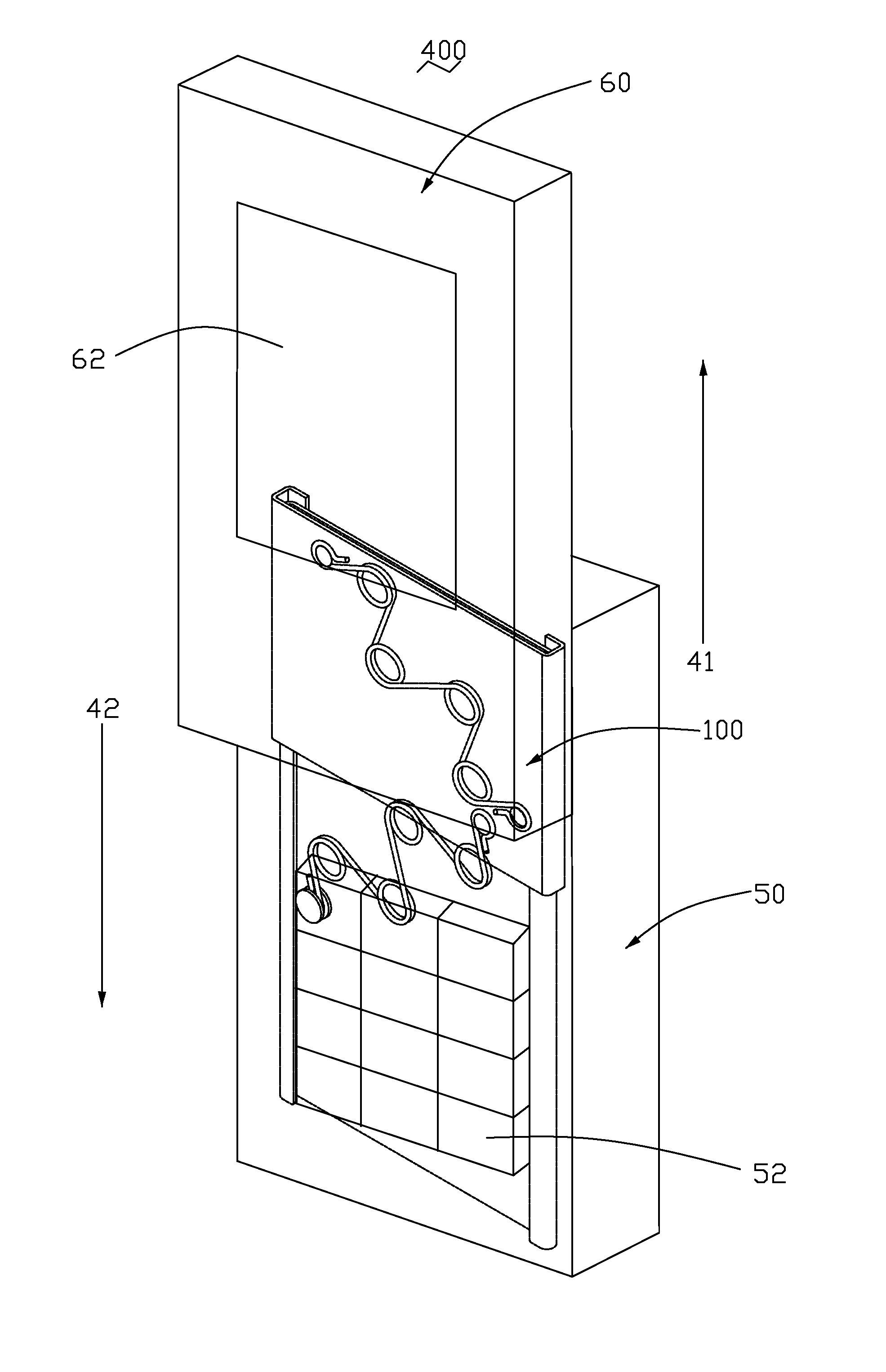
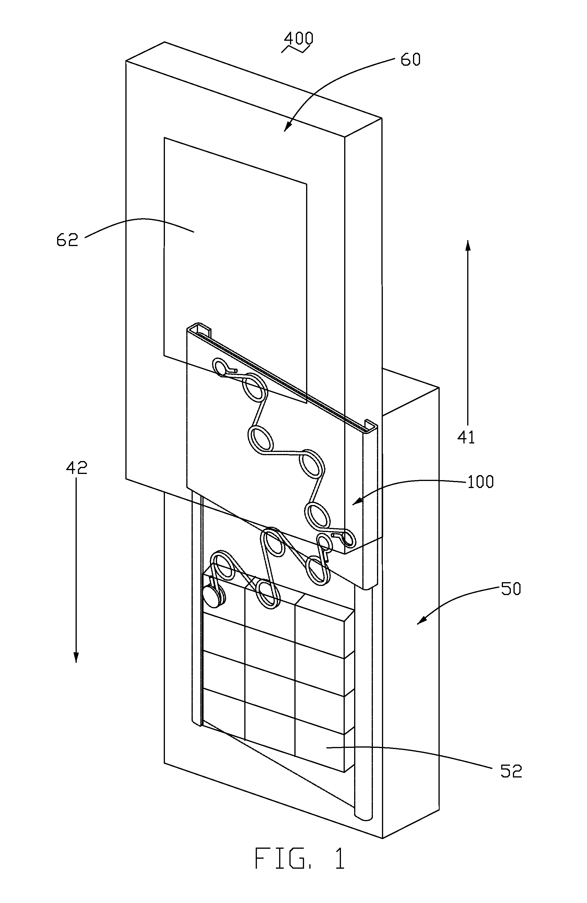
[0022]Referring to FIG. 1, a mobile phone terminal 400 having a sliding-type mechanism 100 is shown according to one embodiment of the present invention. The mobile phone terminal 400 includes a first housing 50, a second housing 60 facing the first housing 50, and a sliding-type mechanism 100. The sliding-type mechanism 100 is positioned between and engaged with the first housing 50 and the second housing 60 such that the second housing 60 is slidably movable relative to the first housing 50. The first housing 50 has a keypad section 52 facing toward the se...


PUM


Abstract

A sliding-type mechanism for use in a portable electronic device is provided. In one embodiment, the sliding-type mechanism includes a base plate, a slidable plate and a linkage module. The slidable plate is slidably connected to the base plate. The linkage module is positioned between the base plate and the slidable plate and connects the base plate and the slidable plate. The linkage module includes a first and second torsion springs and each torsion spring includes a plurality of spring coils. The first and second torsion springs are configured to drive the slidable plate to slide along the base plate when the slidable plate moves a predetermined range along the base plate.

Description

BACKGROUND OF THE INVENTION[0001]1. Field of the Invention[0002]The present invention generally relates to a sliding-type mechanism and, more particularly, to a sliding-type mechanism having at least one torsion spring and a portable electronic device using the same.[0003]2. Description of Related Art[0004]A typical mobile phone terminal provides wireless communication services to its subscriber while wirelessly communicating with its base station. Rapid development in the field of information and telecommunication technologies has made it possible for mobile users to use a variety of functions and types of mobile phone terminals available on the market. Generally, these mobile phone terminals can be classified into three or more types of terminals including bar-type terminals, flip-type terminals, and foldable terminals.[0005]As more diverse design concepts are introduced into the design of mobile phone terminals, sliding-type mobile phone terminals have also come into widespread u...

Claims


Application Information

Patent Timeline
Patent Type & Authority Applications(United States)
IPC IPC(8): H04M1/00F16F1/12H04M1/02
CPCH04M1/0237H04B1/38
Inventor HO, PO-FENG
Owner FIH (HONG KONG) LTD
Learn More