Mountable retractable screen unit

a retractable screen and unit technology, applied in the direction of movable grilles, ways, shutters/movable grilles, etc., can solve the problems of reducing the service life of the retractable screen, so as to achieve the effect of simple form, easy ripping or torn

Inactive Publication Date: 2006-07-13
CHANDLER CARLTON +1
View PDF25 Cites 22 Cited by
  • Summary
  • Abstract
  • Description
  • Claims
  • Application Information

AI Technical Summary

Benefits of technology

[0005] The inventive structure presents a number of advantages over the prior art. First, the invention is simple to form. The retractable screen unit includes a housing unit made in various shapes and of suitable materials, preferably PVC or rust resistant metal. The housing unit contains a tension rod. The tension rod is utilized to draw out and retract the screen from and to the housing unit. The tension rod also has securing means that allow the tension rod to secure itself to an additional housing unit. The tension rod is capable of being removed and replaced with another tension rod. This feature eliminates the need to replace an entire housing unit in the event the tension rod and / or screen needs to be replaced.
[0006] The additional housing unit may be empty to serve only the purpose of securing the retractable screen, or the additional housing unit may contain another screen to allow the screened area to be extended. Each housing unit also contains a locking means, which locks the screen in place when the screen is extended to prevent slack in the event force is applied directly to the screen. In the preferred embodiment, the locking means is a metal strap that surrounds the outside of the housing unit. The metal strap has two prongs with plastic extended buttons on one prong and open holes on the other prong, which connect and grasp the screen between the prongs. This provides another distinct advantage over the other relatively simple, inexpensive prior art in that the locking means provides additional security and safety by preventing the screen from being pushed forward.
[0007] A mounting device mounts directly to railings, fences or existing structures. Each housing unit is secured to extenders that extend out several inches from the mounting device to allow room between the retractable screen and the railing, fence or existing structure. This is an additional advantage over the prior art in that it provides an additional barrier between people, animals or other objects and the hazards posed by fences, railings, or existing structures. In the preferred embodiment, the mounting device is an aluminum adjustable support arm with non-skid backing. The support arm has pre-cut key hole slots for mounting and may also have pre-defined holes for use of a Velcro Bra to provide additional unit support.
[0008] The screen may be made of suitable, durable materials, including sunscreen fabric, Vinyl or other weather resistant fabric for exterior use and non weather resistant materials for indoor use, which are durable and may not be easily ripped or torn. The screen may also be removable from the tension rod and replaceable with another screen. This feature provides the advantage of not having to replace the entire housing unit should the screen need to be replaced for wear or aesthetic reasons.

Problems solved by technology

However, as a result, retractable screens are also typically flimsy when extended and can easily be pushed forward with very little force, thus providing no security or safety effect.
Although fences and railing provide a degree of safety by preventing people and objects from entering a restricted area, they do not address the inherent dangers posed by the fences and railings themselves.
For example, children or small pets have been known to become lodged in or pass over fences and railings causing serious harm and even death.
Moreover, fences and railings are capable of being compromised over time or during adverse weather conditions, which has led to the unexpected collapse of fences and railings while people were leaning on the structures.

Method used


Image

  • Mountable retractable screen unit
  • Mountable retractable screen unit
  • Mountable retractable screen unit

Examples


Embodiment Construction

:

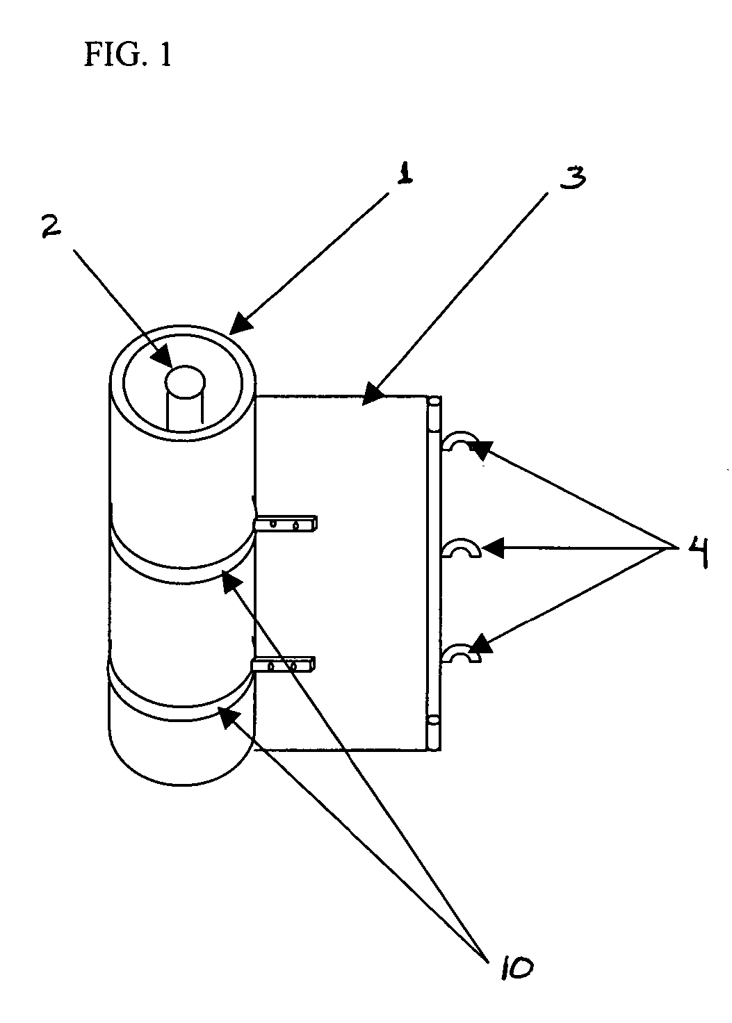
[0013] Shown in FIG. 1 is the housing unit (1) comprising a tension rod (2), the screen (3), wound on the tension rod, and hooks (4) attached to the screen to secure the screen when extended into position along a railing or fence structure.

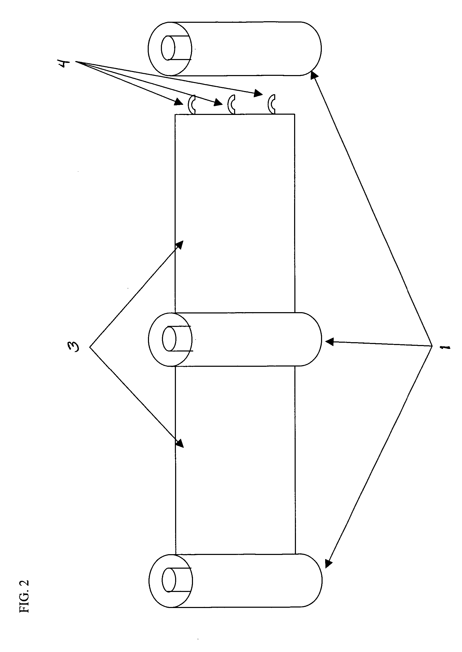
[0014] Multiple housing units may be combined, as reflected in FIG. 2, to extend along a railing or fence structure with each housing unit (1) providing a means to engage the screen (3) of an adjacent housing unit by securing the hooks (4).

[0015] When the screen is extended, the screen may be locked into place, as shown in FIG. 5. The locking device (10) is secured around the outside of the housing unit (1). The locking device (10) has at least one prong (11) with extended buttons (13) and at least one prong (12) with corresponding holes (14) to allow the prongs to connect.

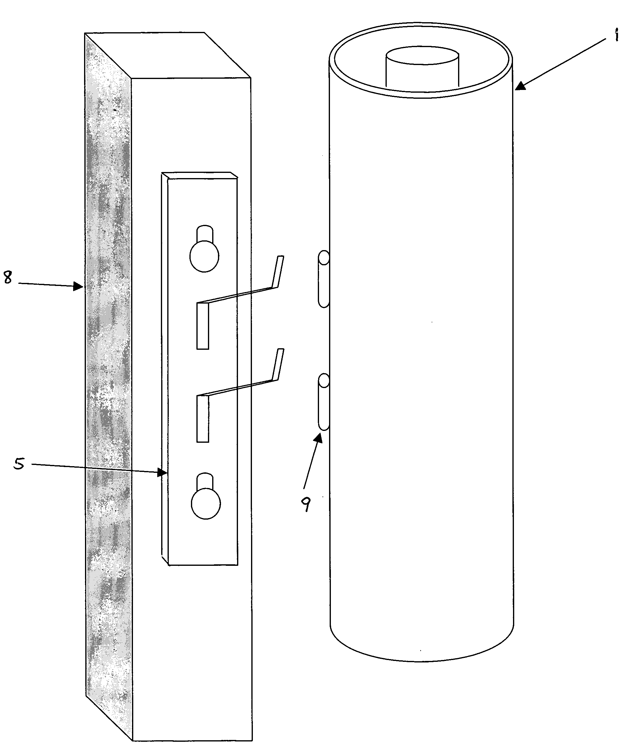
[0016] The housing unit (1) is secured to extenders (7) on the support arm structure (5), such as that reflected in FIG. 3. The support arm structure (5) has pre-cut key hol...


PUM


Abstract

A self-contained, retractable screen unit that may be mounted to any railing system, fence or existing structure to provide additional safety and security.

Description

FIELD OF THE INVENTION [0001] This invention relates to the design and construction of a novel, self-contained, retractable screen unit that may be mounted to any railing system, fence or existing structure to provide additional safety and security. BACKGROUND OF THE INVENTION [0002] Retractable screens exist in various forms serving various functions and are well known in the prior art. Conventionally and ubiquitously, retractable screens that are capable of being mounted to railings, fences or existing structures have been used for the limited purpose of providing decoration and privacy by screening off areas that would otherwise be open to view. The benefit these types of retractable screens provide is that they are typically simple to form and relatively inexpensive. However, as a result, retractable screens are also typically flimsy when extended and can easily be pushed forward with very little force, thus providing no security or safety effect. [0003] Historically, the answer...

Claims


Application Information

Patent Timeline
Patent Type & Authority Applications(United States)
IPC IPC(8): A47H1/00
CPCE01F13/028E06B9/08E06B2009/002
Inventor CHANDLER, CARLTONNITER, ALFRED
Owner CHANDLER CARLTON
Why Eureka
Try Eureka