Condensate recovery and treatment system

a condensate and treatment system technology, applied in the field of recovery devices, can solve the problems of affecting the ease, the use of additional mounting brackets for the filter assembly unit is not desired, etc., and achieve the effects of efficient condensate divert, compact size, and sturdy construction

Inactive Publication Date: 2009-08-25
RECTORSEAL LLC
View PDF1 Cites 21 Cited by
  • Summary
  • Abstract
  • Description
  • Claims
  • Application Information

AI Technical Summary

Benefits of technology

[0005]The primary object of this invention is to provide a condensate recovery and treatment system for use in association with an air conditioning system or other condensate producing systems, which safeguards the condensate producing system from back-flow of fluids and fumes, treats the condensate in a manner that is safe to operators and the surrounding environment, and efficiently diverts the condensate after treatment for constructive use. It is also an object of this invention to provide a condensate recovery and treatment system that has a sturdy construction, is compact in size, and is made from durable materials for extended use. A further object of this invention is to provide a condensate recovery and treatment system that can be promptly, easily, and securely installed. It is also an object of this invention to provide a condensate recovery and treatment system that has redundant protective means configured and positioned within the filter assembly unit to prevent sanitizing / disinfecting vapors in the treatment chamber from backing up and reaching the air conditioning system from which the condensate was derived. A further object of this invention is to provide a condensate recovery and treatment system with easy maintenance access for operators. It is a further object of this invention to provide a condensate recovery and treatment system that can be easily installed in new construction, as well as retrofitted to air conditioning systems in existing construction. It is also an object of this invention to provide a condensate recovery and treatment system that does not sweat when installed in an overhead position in an indoor maintenance area or garage.

Problems solved by technology

Further, the use of additional mounting brackets for the filter assembly unit is not desired as they could potentially interfere with the ease by which its bottom cover can be repeatedly removed as needed for inspection and / or cleaning.

Method used


Image

  • Condensate recovery and treatment system
  • Condensate recovery and treatment system
  • Condensate recovery and treatment system

Examples


Embodiment Construction

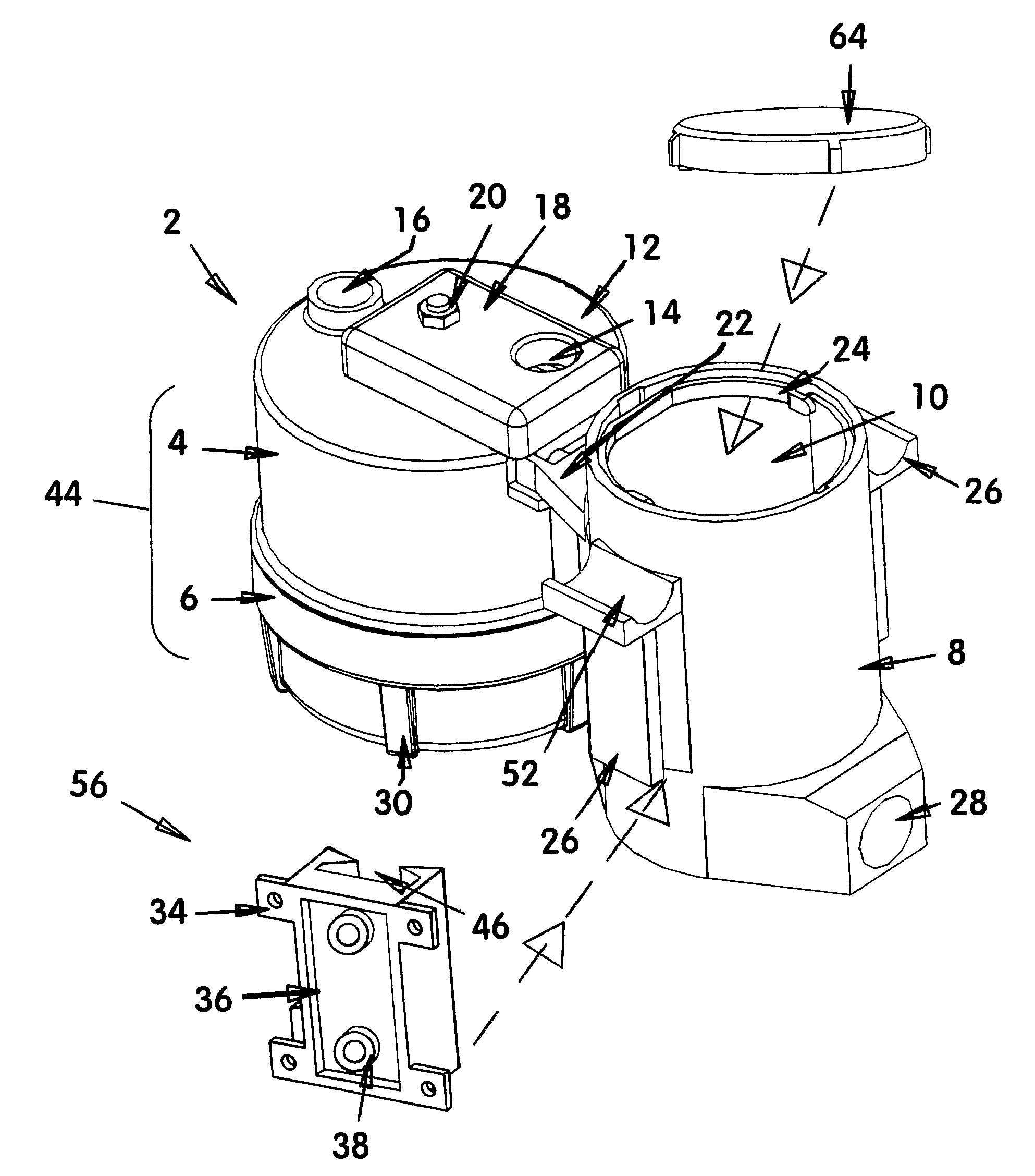
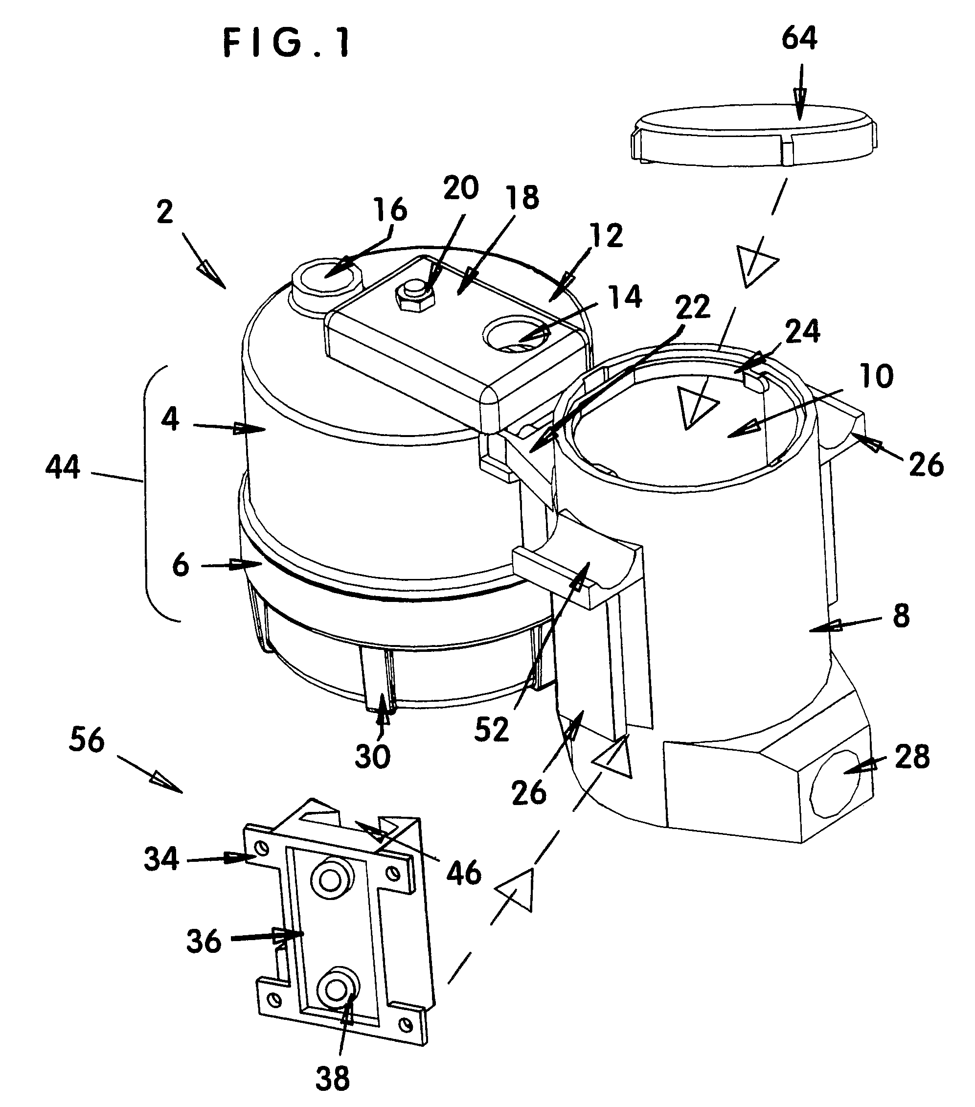
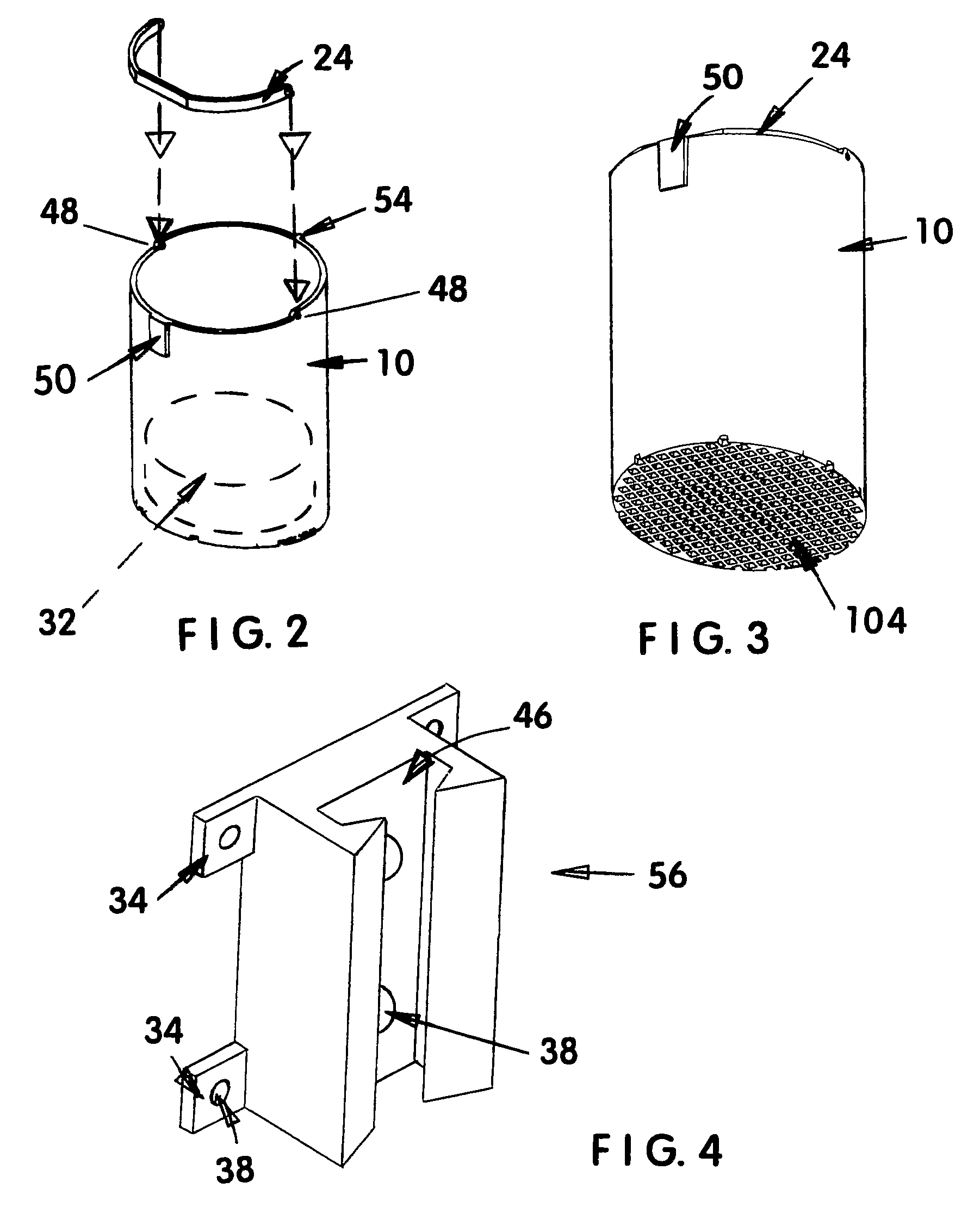
[0024]FIGS. 1 and 5-8 show the most preferred embodiment 2 of the present invention having a treatment chamber 8 connected to and in fluid communication with a filter assembly unit 44 that comprises a filter assembly housing 4, a removable top cover 18, a removable bottom cover 6, and a connecting brace 66. Treatment chamber 8 has a discharge opening 28 positioned remotely from its connection to filter assembly unit 44, a removable cap 64, an interior basket 10 with a rotatable handle 24, and two opposing mounting support appendages 26 that laterally depend from opposing sides of its outer surface. Although not critical, it is preferred that mounting support appendages 26 be positioned perpendicular to the alignment of filter assembly housing 6 to treatment chamber 8. As shown in FIG. 9, it is contemplated for bottom cover 6 to have a threaded connection to the lower end of filter assembly housing 4, although other waterproof and removable connections are also considered to be withi...


PUM

PropertyMeasurementUnit
heightaaaaaaaaaa
pressureaaaaaaaaaa
spaced-apart distanceaaaaaaaaaa

Abstract

A combination filter assembly housing (4) and treatment chamber (8) for use in recovering and sanitizing condensates from air conditioning systems and other sources with vapors released from dissolvable tablets (32), such as those used for treating swimming pool water or laundering purposes. Filter assembly housing (4) has a removable bottom cover, an internal p-trap and valve structure configured to reduce the likelihood of treatment vapors from treatment chamber (8) traveling back through filter assembly housing (4) and entering the associated condensate producing system. Applications can include, but are not limited to, use with systems that replenish water lost from swimming pools due to evaporation, to provide water for filling toilets, pressure washing, cleaning, and other gray water uses, and to provide potable water in areas where is in limited supply.

Description

CROSS-REFERENCES TO RELATED APPLICATIONS[0001]NoneTECHNICAL FIELD[0002]This invention relates to the field of recovery devices for water extracted from the atmosphere, specifically to a combination filter assembly unit and disinfection / sanitizing treatment chamber for use as a primarily gravity-assisted water saving system. It is contemplated for the filter assembly unit to be positioned upstream of the disinfection / sanitizing treatment chamber. The present invention can be connected between a condensate discharge tube, such as the discharge tube of an air conditioning system, and a receiving conduit used to divert the treated condensate for constructive use. Optionally, one or more additional treatment and / or safety devices may be connected between the disinfection / sanitizing treatment chamber and the receiving conduit, such as but not limited to charcoal filters, micron pore filters, holding tanks, and air venting apparatus. The filter assembly unit has a compact configuration and...

Claims


Application Information

Patent Timeline
Patent Type & Authority Patents(United States)
IPC IPC(8): C02F3/12B01D15/00F25D21/14E03B11/00B01D24/38
CPCF25D21/14C02F1/688C02F2103/42F24F2203/12F24F2013/227Y10T137/4891
Inventor CANTOLINO, CHRISTOPHER RALPH
Owner RECTORSEAL LLC
Why Eureka
Try Eureka