Luminescent device and method for manufacturing the same

a technology manufacturing methods, which is applied in the direction of photoelectric discharge tubes, electric discharge lamps, instruments, etc., can solve the problems of deterioration poor productivity low efficiency of light emitting diodes, etc., and achieves the effect of small size and simple construction

Inactive Publication Date: 2007-06-28
KK TOSHIBA
View PDF10 Cites 50 Cited by
  • Summary
  • Abstract
  • Description
  • Claims
  • Application Information

AI Technical Summary

Benefits of technology

[0014] Accordingly, one object of the present invention is to provide a luminescent device which ca

Problems solved by technology

As the operation temperature rises, the efficiency of the light emitting diode lowers, and when the operation temperature becomes higher than 130° C., the deterioration of the light emitting diode itself proceeds.
However, when additional parts are introduced like these, the number of the parts of the luminescent device is increased, the constitu

Method used


Image

  • Luminescent device and method for manufacturing the same
  • Luminescent device and method for manufacturing the same
  • Luminescent device and method for manufacturing the same

Examples


Embodiment Construction

[0023] Referring now to the drawings, wherein like reference numerals designate identical or corresponding parts throughout the several views, the embodiments of this invention will be described below.

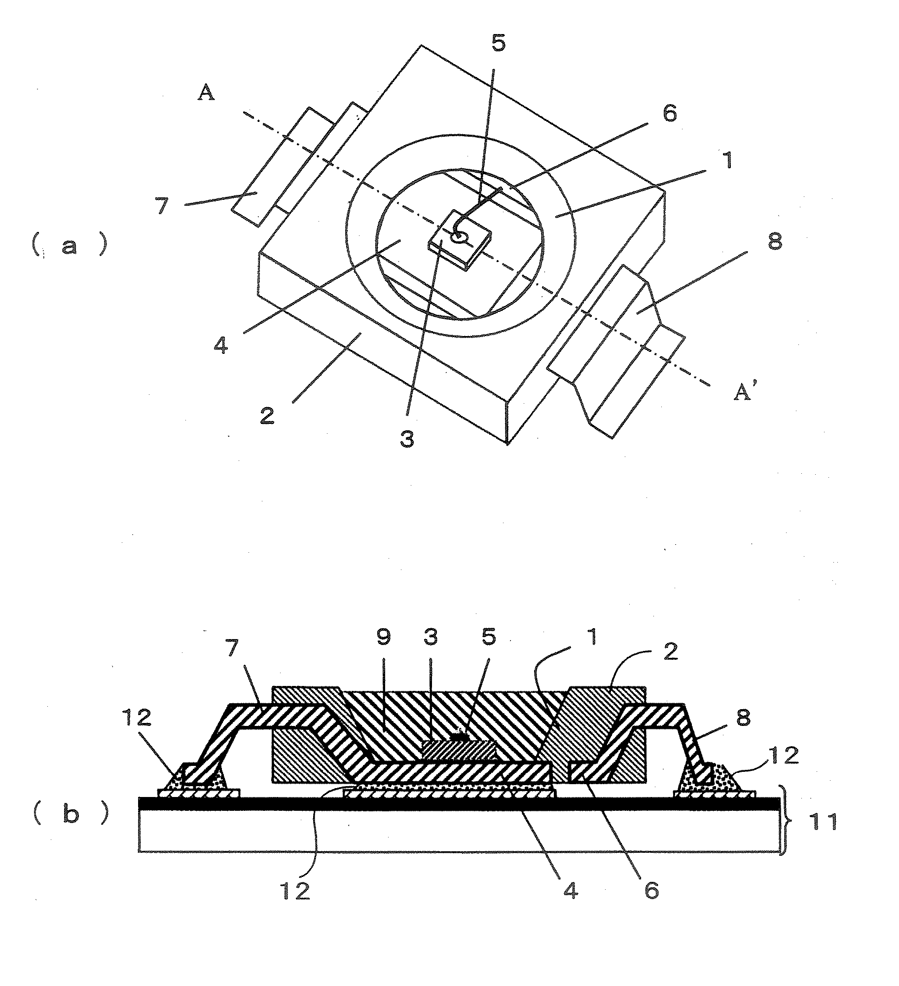
[0024]FIG. 1(a) shows a perspective view of a luminescent device according to an embodiment of this invention, and FIG. 1(b) shows a sectional view of a line A-A′ of the luminescent device of the embodiment shown in FIG. 1(a).

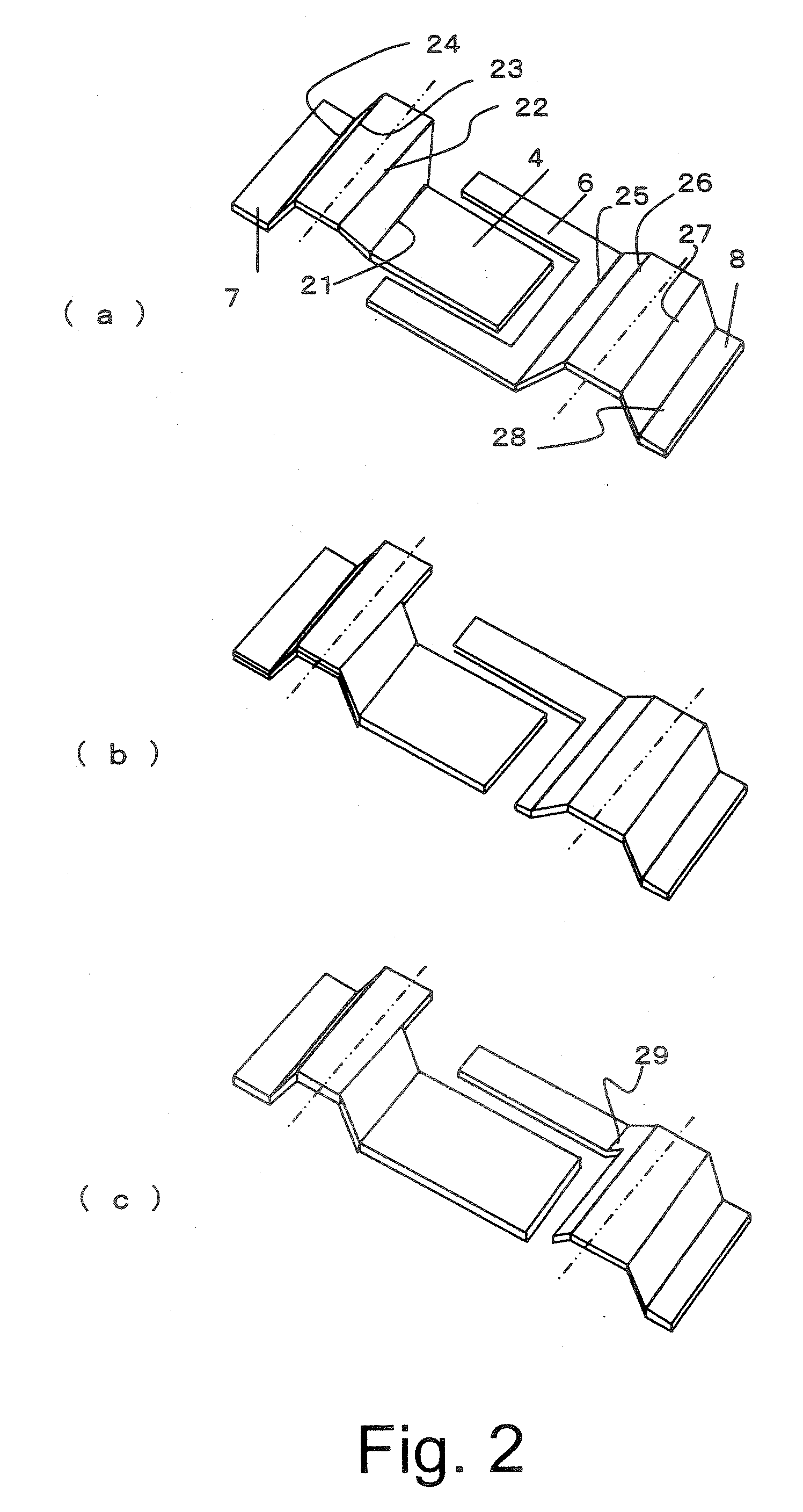
[0025] The luminescent device shown in FIG. 1(a) is composed of a case 2 having an opening 1 in a conical shape, a light emitting diode chip 3 exposed on the bottom of opening 1 in the conical shape, an inner lead 4 on a die pad side for forming a die pad to which the light emitting diode chip 3 is mounted, a wire 5 extending from an electrode on the surface of light emitting diode chip 3, an inner lead 6 on a wire pad side for forming a wire pad to which the other end of wire 5 is connected, an outer lead 7 on the die pad side which is continued to inner lead 4...


PUM


Abstract

A luminescent device including a die pad lead composed of an inner lead and an outer lead, a case for uniting the inner lead, a light emitting diode chip mounted on a first predetermined position of one main surface of the inner lead, and a transparent sealing material portion for sealing the light emitting diode chip and a part of the one main surface. The case seals the inner lead other than an area sealed by the transparent sealing material portion, and the inner lead of the die pad lead has bending portions at least two places including a first bending portion and a second bending portion. A rear of the first predetermined position in the inner lead of the die pad lead is exposed outside the case, and the second bending portion is formed in the case so that the outer lead extends from a side of the case.

Description

CROSS-REFERENCE TO RELATED APPLICATIONS [0001] This application is based upon and claims the benefit of priority from the prior Japanese Patent Application No. 2005-376253, filed on Dec. 27, 2005; the entire contents of which are incorporated herein by reference. BACKGROUND OF THE INVENTION [0002] 1. Field of the Invention [0003] The present invention relates to a luminescent device and a method for manufacturing the same, and more particularly to a luminescent device composed of a light emitting diode having high heat radiation and a method for manufacturing the same. [0004] 2. Description of the Background [0005] In a conventional luminescent device, a pair of leads is combined by the transparent resin which was shaped by molding. At an end of an inner lead of a first lead, a light emitting diode is mounted, and an electrode of the light emitting diode and an end of an inner lead of a second lead are connected by a metal wire. [0006] Outer leads of the first and second leads are b...

Claims


Application Information

Patent Timeline
IPC IPC(8): H01L33/00H01L33/50H01L33/62H01L33/64
CPCH01L33/486H01L2224/48091H01L2224/48247H01L2924/00014H01L2224/45144H01L2924/00H01L2924/10253H01L2924/181H01L2924/00012
Inventor TOMIOKA, TAIZOSUZUKI, TAKAHIROTOKUBO, HIROYUKIAOKI, YUKINORI
Owner KK TOSHIBA
Why Eureka
Try Eureka