Battery system with battery cells arranged in array alignment

a battery system and array alignment technology, applied in the field of batteries, can solve the problems of increasing noise level of the cooling structure, reducing the cooling efficiency of the cooling system with time, and difficulty in air quickly cooling the battery system in the state, so as to efficiently and quietly cool the rectangular batteries, simple arrangement, and efficient cooling

Active Publication Date: 2013-04-02
SANYO ELECTRIC CO LTD
View PDF25 Cites 48 Cited by
  • Summary
  • Abstract
  • Description
  • Claims
  • Application Information

AI Technical Summary

Benefits of technology

[0008]The aforementioned battery system can efficiently cool the rectangular batteries with the cooling pipe and can be simply arranged. Particularly in the case where a battery system includes a number of rectangular batteries that are arranged in array alignment, the aforementioned battery system can efficiently and quietly cool the rectangular batteries with the simple arrangement. The reason is that the aforementioned battery system includes the cooling pipe arranged on the surface of the battery block in a thermally-coupled state so that the rectangular batteries are cooled by the coolant, which is circulated through the cooling pipe.
[0021]Also, in an aspect of the battery system according to the present invention in which the battery block includes a plurality of battery units, the plurality of battery units being aligned from the inlet side to the outlet side of the coolant, and the parallel piping portions of the cooling pipe that are arranged in the battery unit in the outlet side of the colorant are arranged more tightly than the parallel piping portions of the cooling pipe that are arranged in the battery unit on the colorant inlet side, it is possible to efficiently cool the battery unit in the outlet side of the coolant, and as a result it is possible to uniformly cool the entire battery block that includes a plurality of battery units.

Problems solved by technology

In particular, in the case of a battery system used as a power supply device for a vehicle, the battery system is discharged with a large amount of current when the vehicle is accelerating, and the battery system is charged with a large amount of current during regenerative braking or the like.
However, since the thermal capacity of air is small, it is difficult for air to quickly cool the battery system in the state where its batteries generate a significantly large amount of heat.
Also, in this case, there is a disadvantage in that, if the amount of air flow is increased to increase the amount of battery heat reduction, the noise level of the cooling structure increases.
In the case of a cooling structure that cools the battery system by forcedly flowing air, there is a disadvantage in that dust in air accumulates on the surface of the battery system so that the cooling efficiency of the cooling system decreases with time.
This structure can efficiently cool the rectangular batteries with the cooling water, however, since the cooling pipe is arranged between a number of rectangular batteries, in the case of a battery system with a number of aligned rectangular batteries, the arrangement of the cooling pipe is very complicated.

Method used


Image

  • Battery system with battery cells arranged in array alignment
  • Battery system with battery cells arranged in array alignment
  • Battery system with battery cells arranged in array alignment

Examples


Embodiment Construction

)

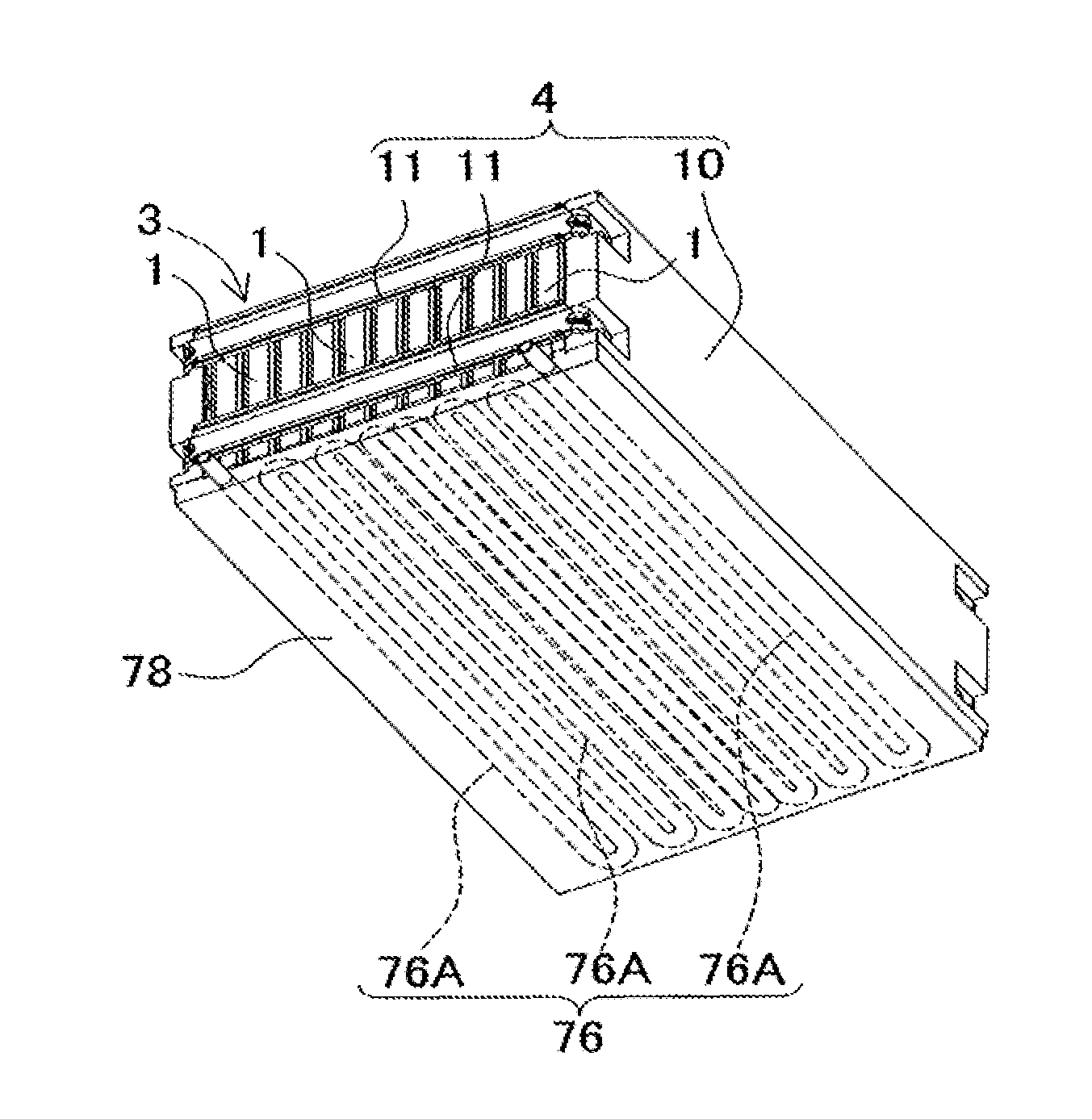
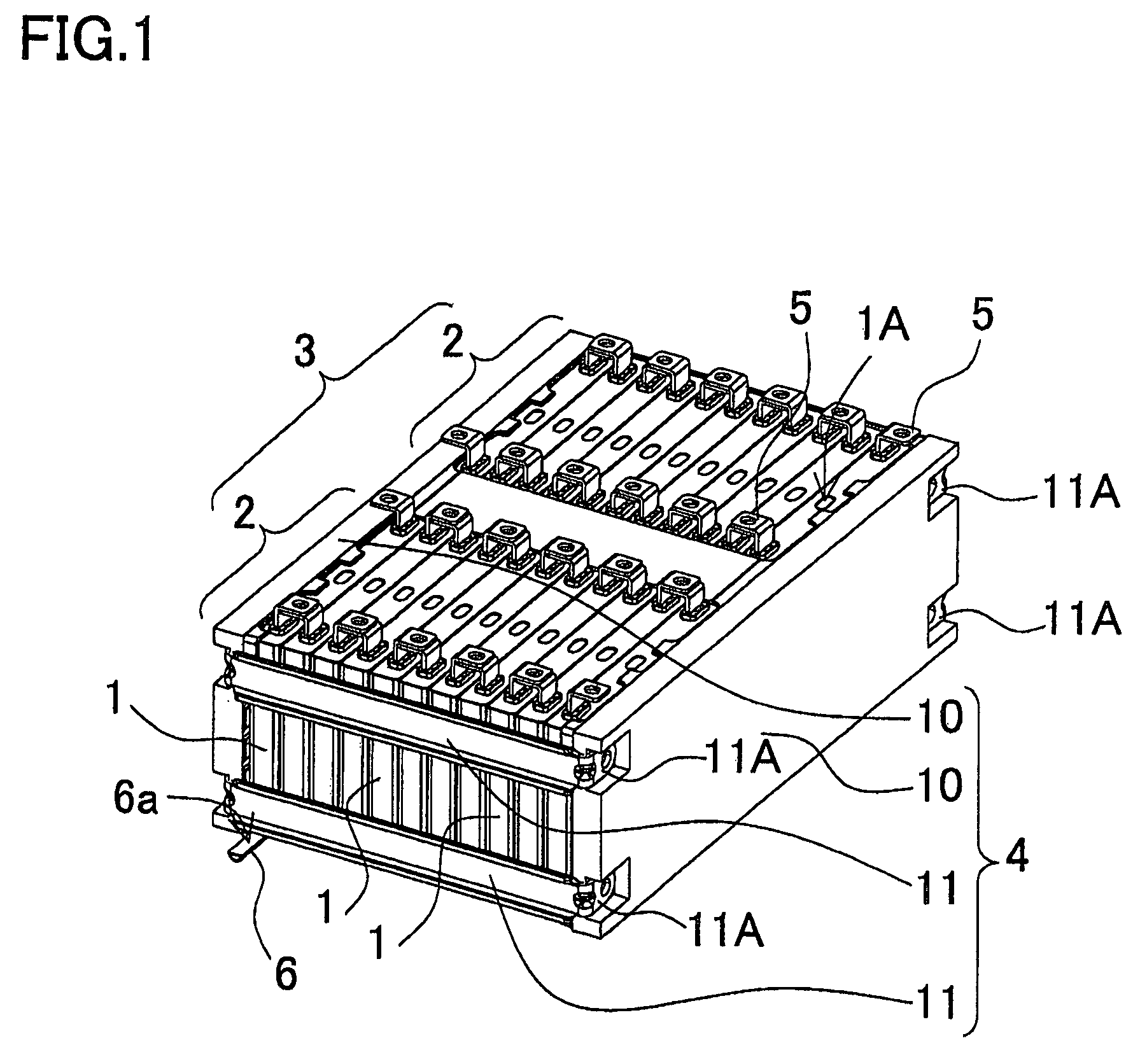
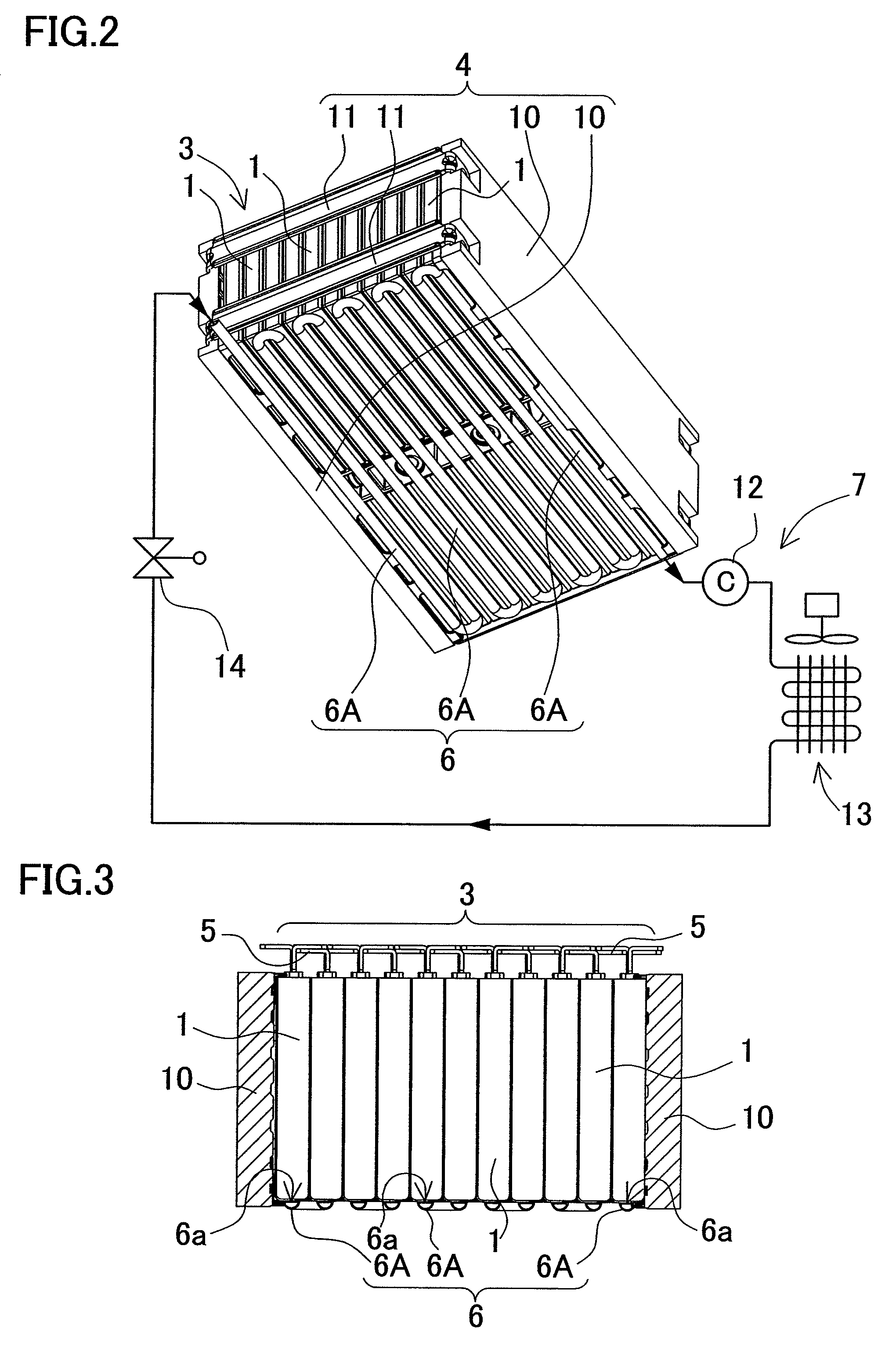
[0076]FIGS. 1 to 3 show a first embodiment. FIGS. 4 to 6 show a second embodiment. FIGS. 7 and 8 show a third embodiment. FIGS. 9 and 10 show a fourth embodiment. FIGS. 11 to 13 show a fifth embodiment. FIGS. 14 to 16 show a sixth embodiment. FIGS. 17 to 19 show a seventh embodiment. FIGS. 20 to 22 show an eighth embodiment. FIGS. 23 and 24 show a ninth embodiment. FIGS. 25 to 27 show a tenth embodiment. FIG. 28 shows an eleventh embodiment.

[0077]FIGS. 29 to 31 show a twelfth embodiment. FIGS. 32 and 33 show a thirteenth embodiment. FIGS. 34 and 35 show a fourteenth embodiment. FIGS. 36 and 37 show a fifteenth embodiment. FIGS. 38 to 40 show a sixteenth embodiment. FIGS. 41 and 42 show a seventeenth embodiment. FIGS. 43 and 44 show an eighteenth embodiment. FIGS. 45 and 46 show a nineteenth embodiment. FIGS. 47 and 48 show a twentieth embodiment. In these Figures, components that are the same as or similar to those of other Figures are labeled with the same reference letters or num...


PUM

PropertyMeasurementUnit
widthaaaaaaaaaa
thicknessaaaaaaaaaa
densityaaaaaaaaaa

Abstract

A battery system includes a battery block, a cooling pipe, and a coolant feeding device. The battery block includes a plurality of rectangular batteries that have a width greater than a thickness and are securely arranged in array alignment by a battery holder. The cooling pipe cools the rectangular batteries of the battery block. The coolant feeding device feeds coolant to the cooling pipe. In the battery system, the cooling pipe is arranged on the surface of the battery block in a thermally-coupled state so that the rectangular batteries are cooled by the coolant, which is circulated through the cooling pipe.

Description

BACKGROUND OF THE INVENTION[0001]1. Field of the Invention[0002]The present invention relates to a battery system that includes a battery block that includes a plurality of rectangular batteries arranged in array alignment and cools the battery block with coolant, and in particular to a battery system suitable for a power supply for vehicles such as hybrid cars.[0003]2. Description of the Related Art[0004]In the case of a battery system with a number of rectangular batteries, since the output voltage of the battery system can be high, the battery system is charged / discharged with a large amount of current. In particular, in the case of a battery system used as a power supply device for a vehicle, the battery system is discharged with a large amount of current when the vehicle is accelerating, and the battery system is charged with a large amount of current during regenerative braking or the like. Since the temperature of battery systems rises greatly when the battery systems are cha...

Claims


Application Information

Patent Timeline
Patent Type & Authority Patents(United States)
IPC IPC(8): H01M10/50H01M50/209H01M50/289
CPCH01M2/1077H01M10/5004H01M10/5008H01M10/5032H01M10/5059H01M10/5075H01M10/5016H01M2/0217H01M10/5079H01M10/625H01M10/647H01M10/6569H01M10/6557H01M10/6567H01M10/617H01M10/613Y02E60/10H01M50/103H01M50/209H01M50/289
Inventor OKADA, WATARUSHIMIZU, HIDEONAKAMURA, SHINSUKEOMURA, TOMOYUKI
Owner SANYO ELECTRIC CO LTD
Why Eureka
Try Eureka