
Ventilation System Employing Sychronized Delivery of Positive and Negative Pressure Ventilation

a ventilation system and positive pressure technology, applied in the field of mechanically assisted ventilatory support, can solve the problems of difficult maintenance of seals, difficult to efficiently communicate the negative extrathoracic pressure to the patient, and several limitations of the negative pressure system

Inactive Publication Date: 2008-06-26
RIC INVESTMENTS LLC
View PDF6 Cites 8 Cited by
  • Summary
  • Abstract
  • Description
  • Claims
  • Application Information

AI Technical Summary

Benefits of technology

[0015]These and other objects, features, and characteristics of the present invention, as well as the methods of operation and functions of the related elements of structure and the combination of parts and economies of manufacture, will become more apparent upon consideration of the following description and the appended claims with reference to the accompanying drawings, all of which form a part of this specification, wherein like reference numerals designate corresponding parts in the various figures. It is to be expressly understood, however, that the drawings are for the purpose of illustration and description only and are not intended as a definition of the limits of the invention.

Problems solved by technology

Negative pressure systems have several limitations.
These seals are difficult to maintain.
As a result, it is difficult to efficiently communicate the negative extrathoracic pressure to the patient.
Additionally, negative pressure systems are often limited with respect to triggering and cycling of breaths due to the large compliance of the thoracic interface.
Positive pressure systems, however, have their own distinct limitations.
For example, the effectiveness of a positive pressure system is limited by the ability to maintain a low level of leakage between the patient interface and the patient's face.
Additionally, the pressure at which the supply of breathing gas is delivered is limited by a patient's relatively low glottic opening pressure, which if exceeded, may result in gastric distention.
Furthermore, positive pressure ventilatory support is lost when the patient removes the patient interface, for example, to talk, eat, or drink.

Method used


Image

  • Ventilation System Employing Sychronized Delivery of Positive and Negative Pressure Ventilation
  • Ventilation System Employing Sychronized Delivery of Positive and Negative Pressure Ventilation
  • Ventilation System Employing Sychronized Delivery of Positive and Negative Pressure Ventilation

Examples


Embodiment Construction

[0024]Directional phrases used herein, such as, for example, left, right, clockwise, counterclockwise, top, bottom, up, down, and derivatives thereof, relate to the orientation of the elements shown in the drawings and are not limiting upon the claims unless expressly recited therein.

[0025]As employed herein, the term “number” shall mean one or more than one and the singular form of “a”, “an”, and “the” include plural referents unless the context clearly indicates otherwise.

[0026]As employed herein, the statement that two or more parts are “connected” or “coupled” together shall mean that the parts are joined together either directly or joined together through one or more intermediate parts. Further, as employed herein, the statement that two or more parts are “attached” shall mean that the parts are joined together directly.

[0027]The present invention is directed to a ventilation system which is adapted to synchronize the delivery of both positive pressure ventilation and negative ...


PUM


Abstract

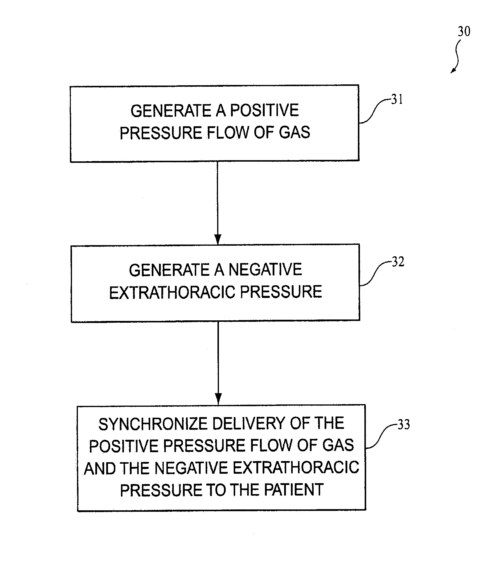
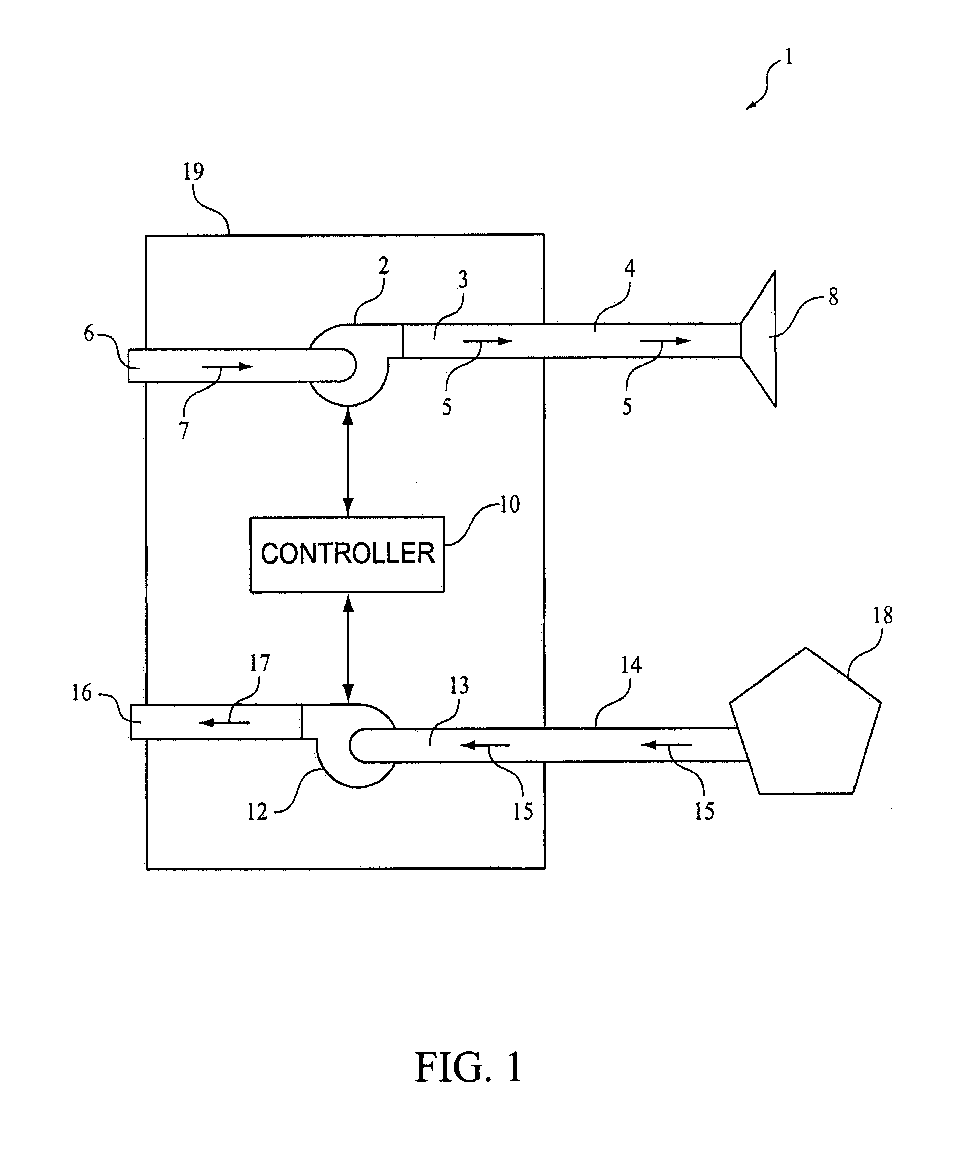
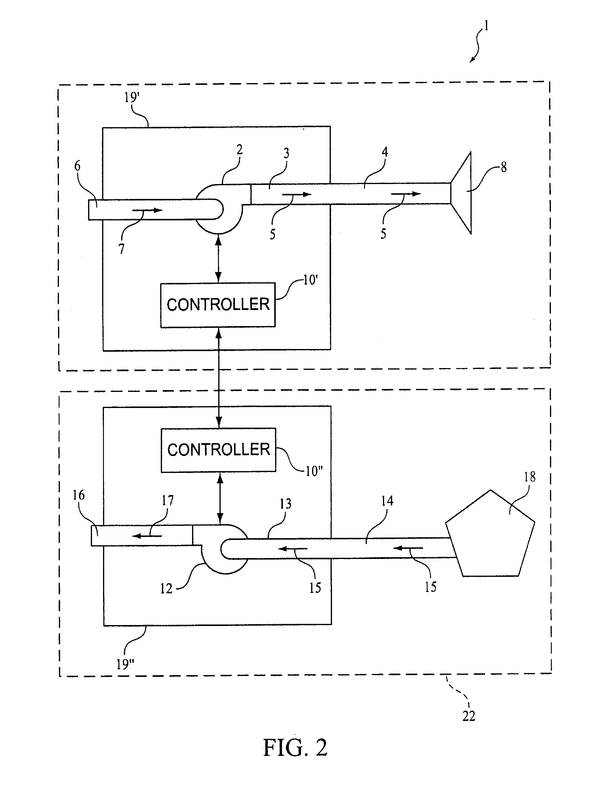
A ventilation system is adapted to synchronize the delivery of both positive pressure ventilation and negative pressure ventilation to a patient. The ventilation system is structured to produce a positive pressure flow of gas which is delivered to the patient's airway and a negative pressure flow of gas which is converted into a negative extrathoracic pressure. The negative extrathoracic pressure is communicated to the patient in synchronism with the delivery of the positive pressure flow of gas.

Description

CROSS-REFERENCE TO RELATED APPLICATIONS[0001]This application claims priority under 35 U.S.C. § 119(e) from provisional U.S. patent application No. 60 / 830,529 filed Jul. 13, 2006 the contents of which are incorporated herein by reference.BACKGROUND OF THE INVENTION[0002]1. Field of the Invention[0003]The present invention pertains to mechanically assisted ventilatory support and more particularly to a ventilation system which synchronizes the delivery of positive pressure ventilation and negative pressure ventilation to provide improved total ventilatory support to a patient.[0004]2. Description of the Related Art[0005]Mechanically assisted ventilatory support may be delivered to a patient either invasively or non-invasively. Invasive ventilation generally requires endotracheal intubation (i.e., insertion of a breathing tube into the patient's airway) or a tracheostomy (i.e., creation of an artificial opening in the patient's trachea to which a breathing tube is inserted). Non-invas...

Claims


Application Information

Patent Timeline
Patent Type & Authority Applications(United States)
IPC IPC(8): A61H31/00
CPCA61H31/02A61H2201/165A61M16/00A61M16/06A61M16/0683A61M16/0069A61M2016/0027A61M2016/003A61M2205/3368A61M2210/0618A61M16/0009A61M16/0816A61M16/0627A61M16/0633A61M16/022
Inventor DOYLE, PETER R.
Owner RIC INVESTMENTS LLC
Learn More