

Beam steering control for mobile antennas
a mobile antenna and beam steering technology, applied in the direction of antennas, electrical devices, antenna supports/mountings, etc., can solve the problems of increasing the requirement for pointing accuracy, angular errors of three degrees, and significant challenges to the tracking algorithm employed by the hos
- Summary
- Abstract
- Description
- Claims
- Application Information
AI Technical Summary
Benefits of technology
Problems solved by technology
Method used
Image

Examples
Embodiment Construction
[0022]In the following description, reference is made to the accompanying drawings which form a part hereof, and which is shown, by way of illustration, several embodiments of the present invention. It is understood that other embodiments may be utilized and structural changes may be made without departing from the scope of the present invention.
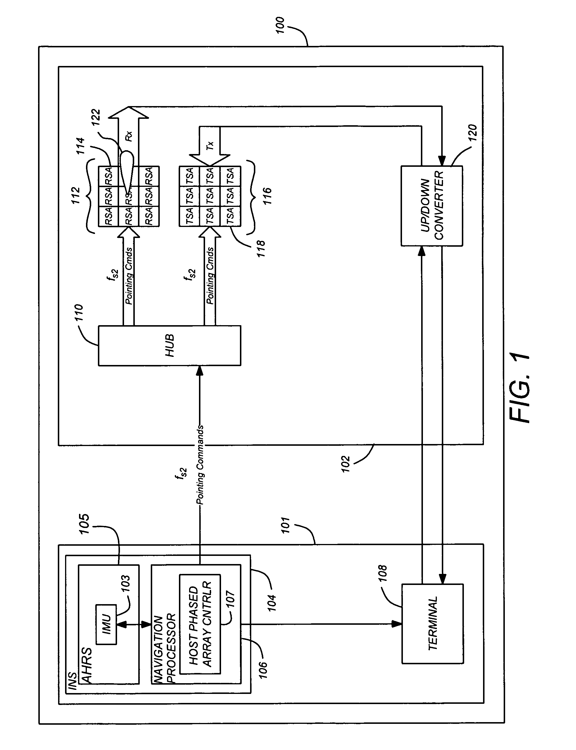
[0023]FIG. 1 is a diagram an exemplary of a prior art phased array beam pointing system 100. The system comprises a platform 101 communicatively coupled to one or more phased array antenna systems (PAASs) 102 (a single PAAS 102 is illustrated). The PAAS 102 may be rigidly coupled to the platform 101 or may be flexibly or rotatably coupled to the platform 101 so as to permit PAAS 102 motion independent of the platform 101. The platform 101 is typically a mobile platform such as moving vehicle of some sort, including a spacecraft or satellite, aircraft, naval vessel, or terrestrial vehicle.
[0024]The platform 101 comprises an attitude and headi...
PUM
 Abstract
Description
Claims
Application Information