Percutaneous heart valve devices

a technology of heart valves and percutaneous injection, which is applied in the field of medical devices, can solve the problems of mechanical valves being susceptible to clot formation, long-term wear and tear of devices, and the device cannot be repositioned

a technology of heart valves and percutaneous injection, which is applied in the field of medical devices, can solve the problems of mechanical valves being susceptible to clot formation, long-term wear and tear of devices, and the device cannot be repositioned

US20080154356A1Inactive Publication Date: 2008-06-26OBERMILLER JOSEPH F +2

Image

  • Percutaneous heart valve devices
  • Percutaneous heart valve devices
  • Percutaneous heart valve devices

Examples


Embodiment Construction

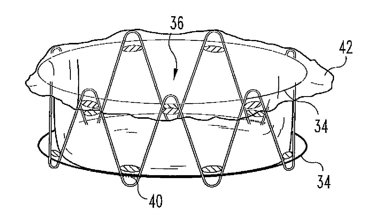
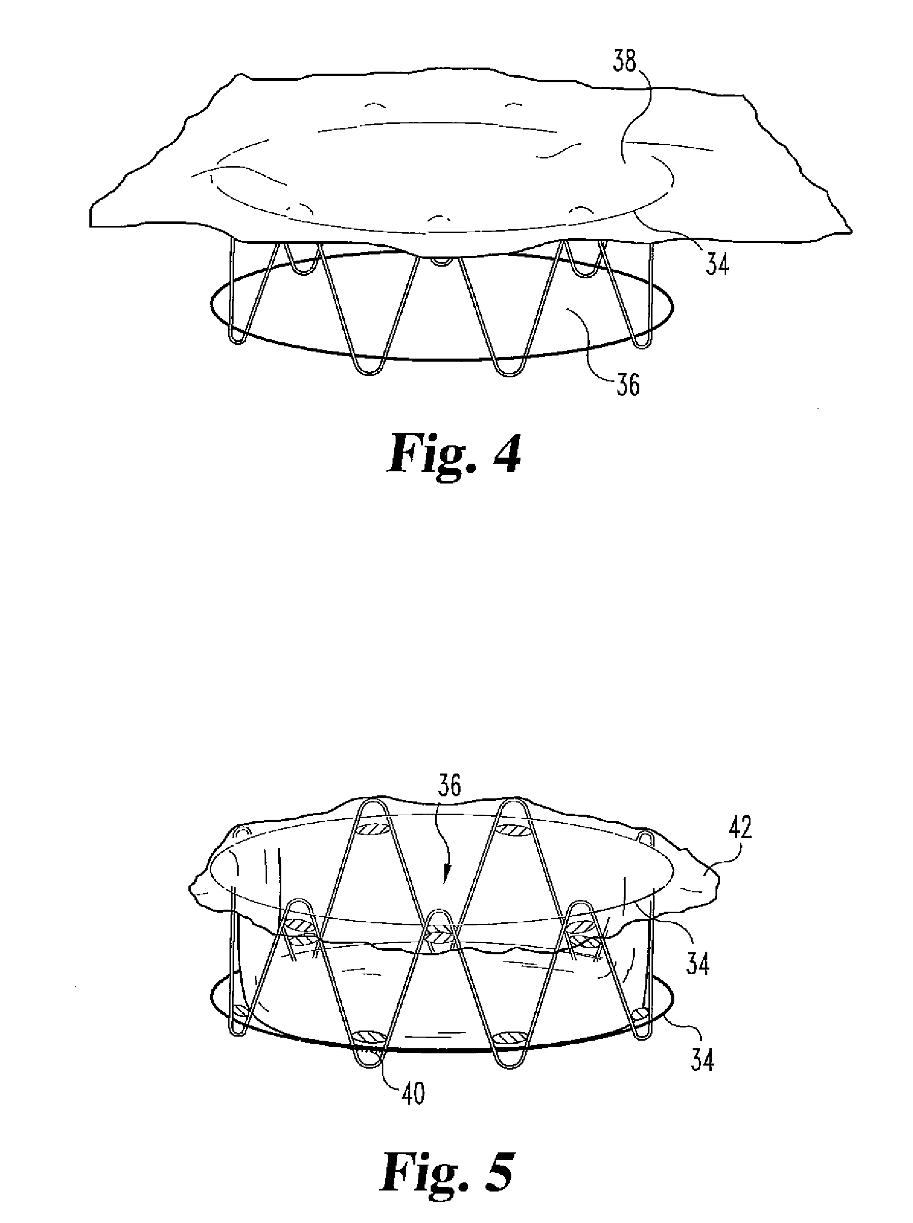
[0018]With reference to FIG. 15, shown is one embodiment of the present invention. The invention includes a frame such as a wire stent that has a lumen extending therethrough. Near one end of the stent is the valve assembly comprising some leaflets or cusps. A valve opening is generally located between the leaflets through which fluid flows. Although shown as a two leaflet valve, equally the invention can comprise, in any embodiment described herein, at least one leaflet such as two, three or four leaflets.

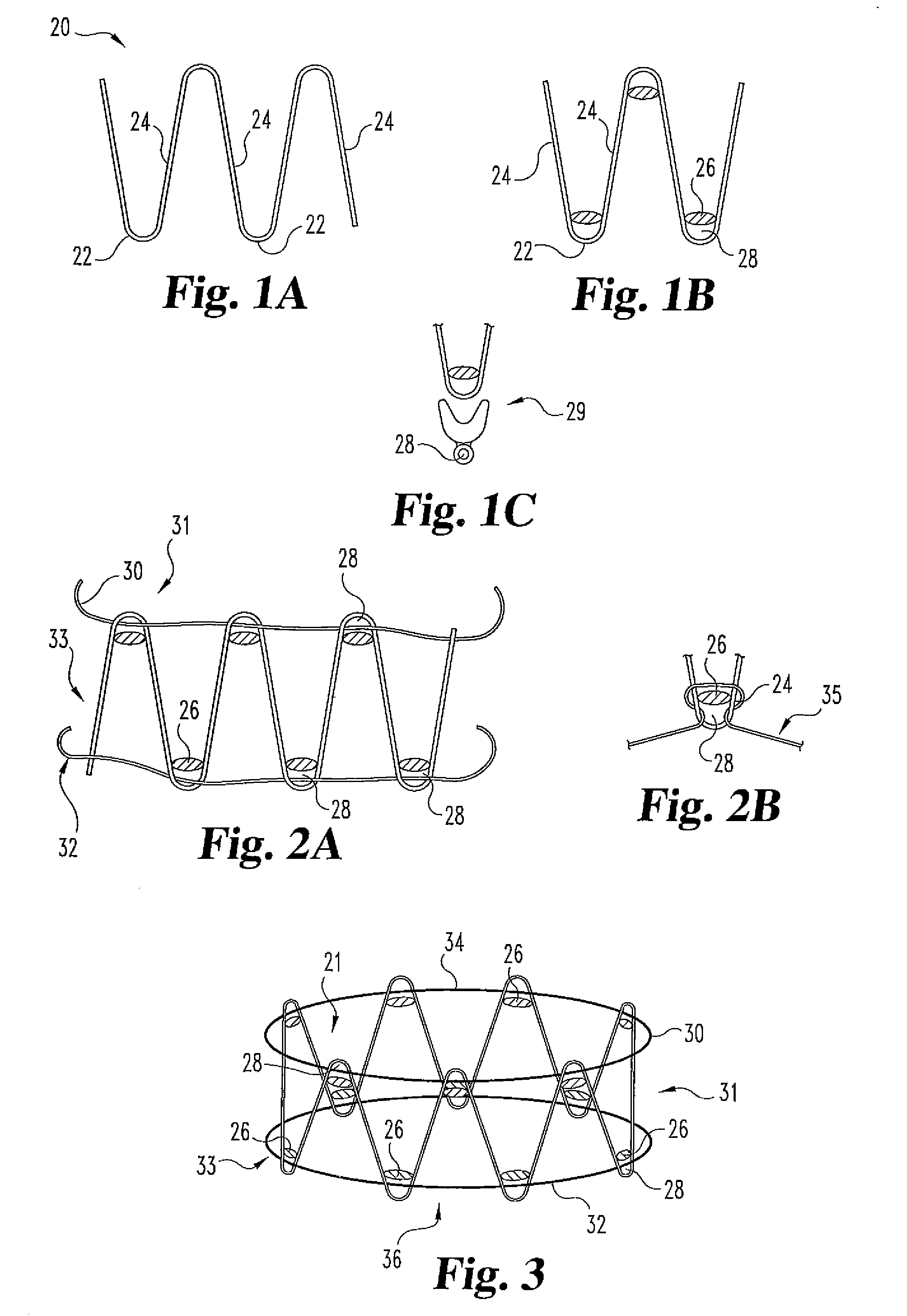
[0019]With respect to FIGS. 1A, 1B, and 1C, a frame is partially shown. The frame can comprise a stent 20. Choices of stent include a self expanding stent or a non-self expanding stent. In one embodiment of the present invention stent 20 is a self expanding stent such as the Gianturco stent available from Cook Inc. of Bloomington, Ind. as described in U.S. Pat. No. 4,580,568, the entire disclosure of which is expressly incorporated by reference herein. Such stent can be any length...


PUM

PropertyMeasurementUnit
lengthaaaaaaaaaa
distanceaaaaaaaaaa
diametersaaaaaaaaaa

Abstract

The invention includes a medical device and more specifically relates to a valve found generally within a frame. In a preferred device, the frame preferably comprises a self-expanding stent frame, and the valve has at least one expandable and contractible pocket member within the stent frame for resisting and permitting fluid flow, respectively.

Description

REFERENCE TO RELATED APPLICATIONS[0001]This is a continuation of U.S. patent application Ser. No. 10 / 837,058, filed on Apr. 30, 2004, pending, which is a continuation of U.S. patent application Ser. No. 10 / 457,148, filed on Jun. 9, 2003, pending, which is a continuation of U.S. patent application Ser. No. 10 / 182,970, filed on filed Jan. 31, 2001, abandoned, which is an National Stage of PCT / US / 01 / 03095, filed on Jan. 31, 2001 and published in English, which claims the benefit of U.S. Provisional Patent Application No. 60 / 179,195, filed on Jan. 31, 2000.BACKGROUND OF THE INVENTION[0002]1. Technical Field of the Invention[0003]The invention includes a medical device and more specifically to a valve found generally within a frame. In preferred devices the frame is comprised of a radially expandable stent which can be delivered through a delivery device such as a catheter.[0004]2. Background of the Invention[0005]Lower extremity venous hypertension in addition to venous insufficiency is...

Claims


Application Information

Patent Timeline
26 Jun 2008
Publication
US20080154356A1
IPC
A61F2/06; A61F2/84; A61F2/24; A61F2/90; A61L27/00
CPC
A61F2/2418; A61F2/2475; A61F2220/0075; A61F2220/005; A61F2220/0016
Inventors
OBERMILLER, JOSEPH F.; OSSE, FRANCISCO JOSE