Entrapping apparatus and method for use

a technology of entrapment apparatus and entrapment method, which is applied in the field of entrapment apparatus and method for use, can solve problems such as the effect of reducing the patient's comfor

Inactive Publication Date: 2001-04-24
ARTEMIS MEDICAL
View PDF69 Cites 1141 Cited by
  • Summary
  • Abstract
  • Description
  • Claims
  • Application Information

AI Technical Summary

Benefits of technology

The support wire may extend through the expandable channel device or catheter, through or around the occlusion and at its distal end has an annular braided element attached thereto. The support wire is a dual element support wire having a core and an annular shell that slides on the core. The distal end of the core is attached to the distal end of the annular braided element and the distal end of the shell is attached to the proximal end of the annular braided element. Thus movement of the core and shell relative to one another moves the braided element from a radially retracted position which is useful for insertion through the catheter to a radially expanded position which expands it to the sidewall of the channel. When the annular braided element is in its radially compressed (smaller diameter) state, it can be passed through or around the occlusion together with the rest of the wire to reside on the distal end of the occlusion. When the braided element is expanded and moved proximally (that is, in a retrograde fashion), it will engage the occlusion and force the occlusion into the catheter. Alternatively, no motion of the engaging element may be required if aspiration is applied. In this case, the engaging expandable channel device acts as a seal to prevent the suction from aspiration to remove much material beyond its point of deployment in the channel. Further, no motion of the distal engaging element is required if the expandable engaging element is moved distally toward the occlusion and thusly engulfs the obstruction by its forward motion and expandability.

Problems solved by technology

However, Dubrul describes the filter occluder specially to keep particulate (e.g. emboli) from travelling downstream and causing deleterious effects on the patient (e.g. stroke).

Method used


Image

  • Entrapping apparatus and method for use
  • Entrapping apparatus and method for use
  • Entrapping apparatus and method for use

Examples


Embodiment Construction

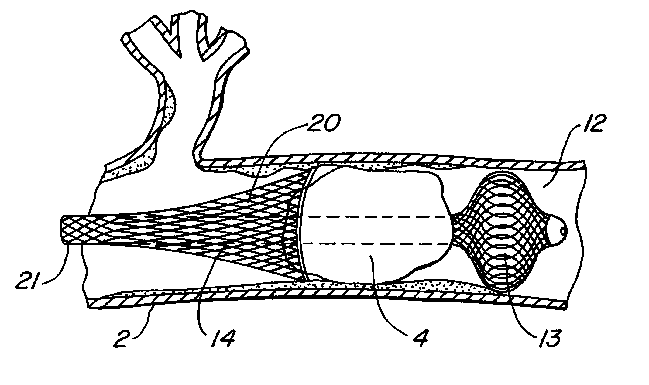
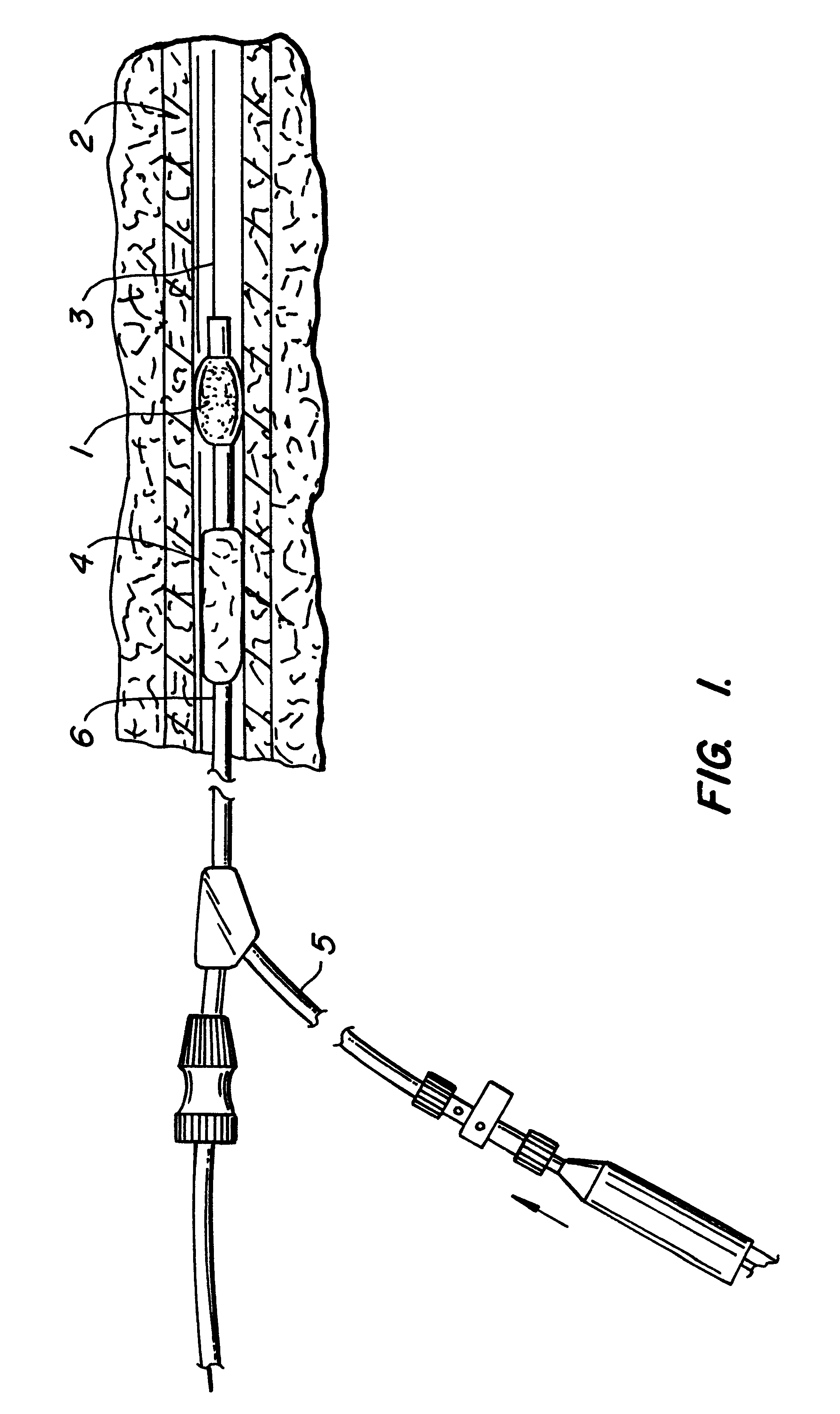
FIG. 1 is a cross sectional drawing showing the device of this invention fully deployed in an occluded channel 2. The FIG. 1 drawing shows the TRAP element at the distal end of the catheter in its radially expanded state. It is important to note that the TRAP element may take a variety of shapes as would be required for the particular application. The preferred shape is likely to be an ovoid shape. FIG. 1 is an illustration of the TRAP device using an inflatable balloon 1. FIG. 1 shows the balloon in its deployed or inflated condition while in position in a tubular channel 2 that is occluded with a thrombus 4. Hence FIG. 1 is an artery or vein 2 and the obstruction 4 is a blood clot. However, the obstruction could be different from a blood clot as described earlier and the tubular channel could be different from a vein or artery. The balloon catheter / TRAP 6 has been inserted into the vessel 2 via a guidewire 3. The balloon is inflated with balloon inflation line 5. Not illustrated i...


PUM


Abstract

Medical devices that have a novel mechanical trap(s) on the distal end of a shaft that is used for the removal of material from the body. Further an expandable channel is included to entrap the material that aid with removal or obliteration of tissue or foreign bodies is disclosed.

Description

In general, this invention relates to medical devices and methods. In particular, the instant invention relates to an improved device for the removal of tissue or foreign bodies from the body. One particular use of this improved device is removal of obstructions from the tubular channels of the body. These obstructions are usually blood clots (thrombi) or other byproducts of occlusive vascular disease (e.g. plaque) or even instruments / implants lost by the physician during an intervention including but not limited to wires, stents, staples, components, embolic coils, etc. Further, the removal of matter from non-vascular channels is disclosed. Even further, the instant invention can be used for the removal of tissue including but not limited to tissue biopsies, cancerous, necrotic, infected, or other diseased tissue from solid or semi-solid tissue.Occlusive vascular disease is a common ailment in people resulting in enormous costs to the health care system. Blood clots are the most co...

Claims


Application Information

Patent Timeline
Patent Type & Authority Patents(United States)
IPC IPC(8): A61B17/22A61M25/00
CPCA61B17/221A61B2017/2212
Inventor DUBRUL, WILLIAM RICHARDFULTON, RICHARD E
Owner ARTEMIS MEDICAL
Why Eureka
Try Eureka