
Structure of automobile pedal

a technology of automobile pedals and structures, applied in the direction of mechanical control devices, instruments, cycle equipments, etc., can solve the problems of metal pedals, needing to be completely replaced by a new one, and poor skid resistance, so as to reduce the consumption of natural resources and replace decorative patterns

Inactive Publication Date: 2008-07-03
GREAT PERFORMANCE INDS CO LTD
View PDF10 Cites 4 Cited by
  • Summary
  • Abstract
  • Description
  • Claims
  • Application Information

AI Technical Summary

Benefits of technology

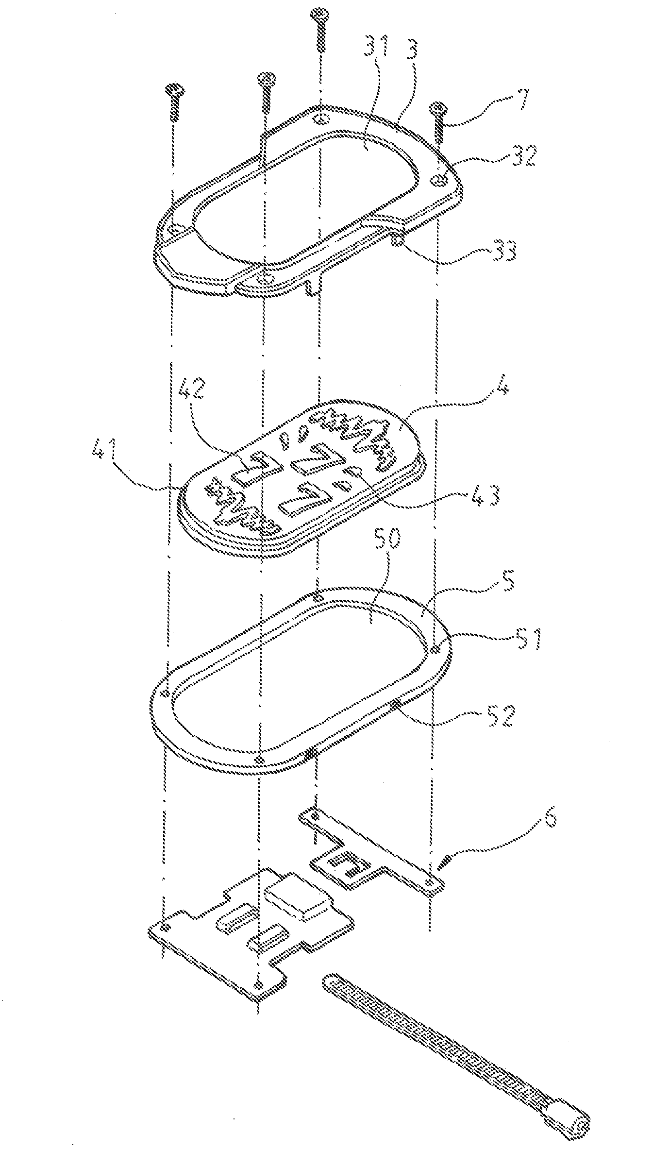
"The present invention is an automobile pedal that features decoration, skid-proofness, and replaceability of decorative patterns. It is made of flexible and soft material, such as rubber, to provide comfort and enhance skid-proofness. The embedded member of the automobile pedal is made of a raised portion with different zones that are formed by micro injection molding to achieve vivid and aesthetic appealing to general consumers. The frame member of the automobile pedal is securely attached to the base board with the embedded member interposed between them using securing tabs and notches. The invention helps to protect the environment by replacing traditional materials with natural resources."

Problems solved by technology

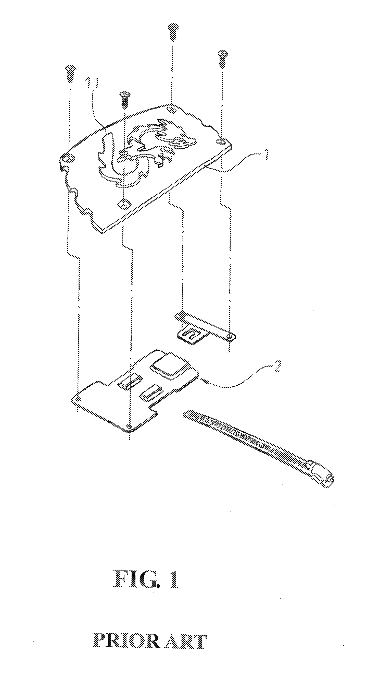
The conventional automobile pedal is made of metal, which in fact is not good for skid-proofness and this is particularly true for a driver who wears shoes having rigid outer soles and attempts to use the rigid-sole shoes to step the pedal.
In addition, since the body is made of metal, once worn out, the pedal has to be completely replaced by a new one.
This causes a great consumption of natural resources for wearing often occurs in a minor portion of the pedal, and is also against environment protection for the amount of waste induced by the disposal of the worn pedal is increased.
This is itself not economic for manufacturing of the automobile pedals.

Method used


Image

  • Structure of automobile pedal
  • Structure of automobile pedal
  • Structure of automobile pedal

Examples


Embodiment Construction

[0019]The following descriptions are of exemplary embodiments only, and are not intended to limit the scope, applicability or configuration of the invention in any way. Rather, the following description provides a convenient illustration for implementing exemplary embodiments of the invention. Various changes to the described embodiments may be made in the function and arrangement of the elements described without departing from the scope of the invention as set forth in the appended claims.

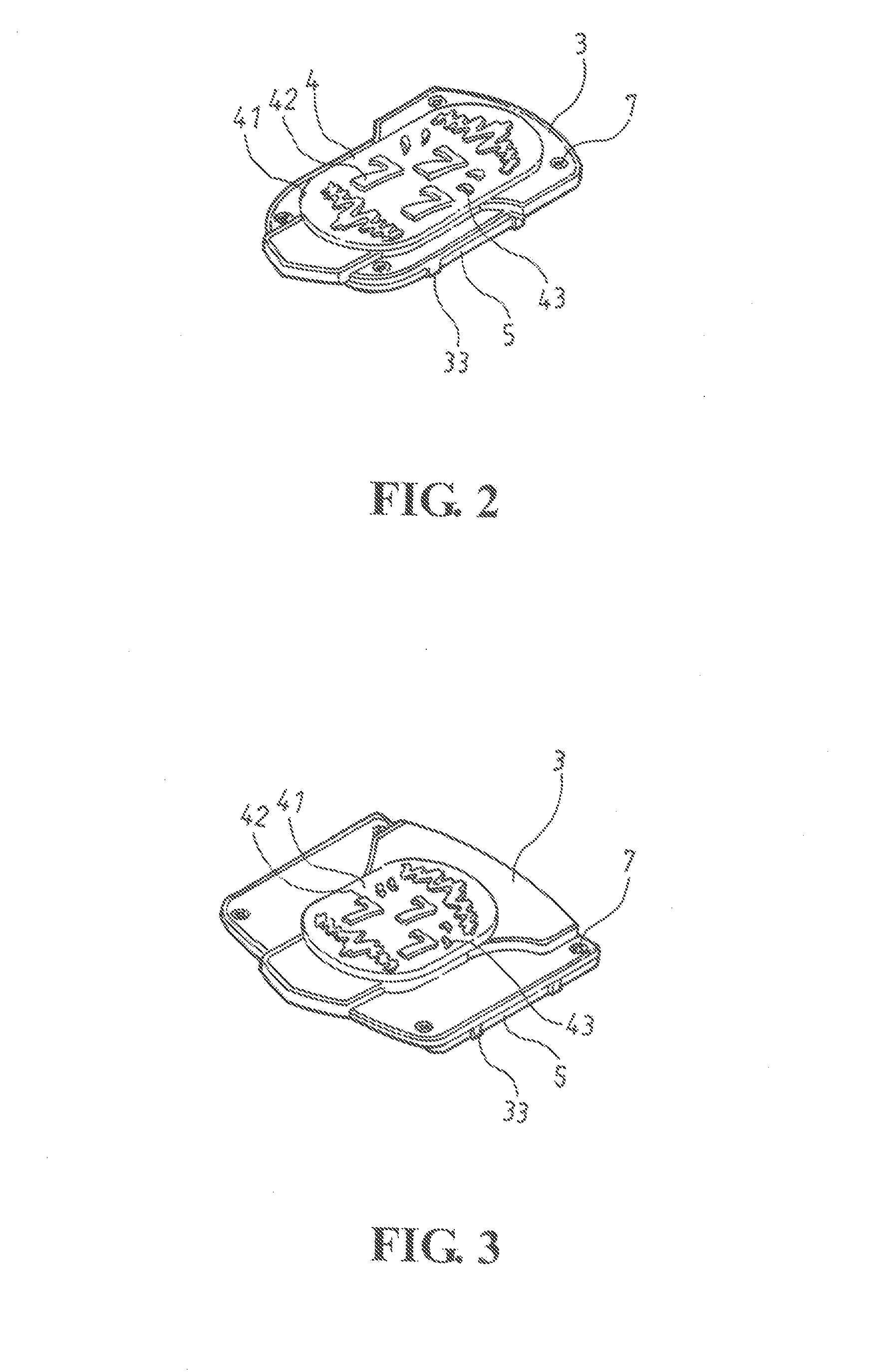
[0020]With reference to the drawings and in particular to FIGS. 2-5, an automobile pedal constructed in accordance with the present invention comprises a frame member 3, an embedded member 4, a base board 5, and a securing structure 6. The frame member 3 forms an opening 31 surrounded by a circumferential wall (not labeled) in which mounting holes 32 are defined A plurality of securing tabs 33 is formed on and distributed along an outer circumference of the circumferential wall and is substantial...


PUM


Abstract

An automobile pedal includes a frame member, an embedded member, a base board, and a mounting structure. The frame member forms an opening. The embedded member forms a raised portion formed on a top thereof. Embossment is formed on die top of the raised portion. Also formed on the raised portion are bosses located around the embossment. The raised portion is fit in the opening of the frame member. A bottom of the embedded member is positioned on the base board and is secured thereto. The base board is also secured to the mounting structure to thereby constitute an automobile pedal, which can be used as an accelerator pedal or a brake pedal and features decoration and skid-proofness as well as replaceability of the embedded member to effect replacement of decoration patterns and to achieve protection of environment.

Description

BACKGROUND OF THE INVENTION[0001](a) Technical Field of the Invention[0002]The present invention relates to an automobile pedal and in particular to an automobile pedal that features decoration and skid-proofness, as well as replaceable patterns and is also conservative for environment.[0003](b) Description of the Prior Art[0004]A conventional automobile pedal such as an accelerator pedal, a brake pedal, and a clutch pedal, as shown in FIG. 1, comprises a body 1 having a top surface embossment 11 and a bottom secured to a mounting structure 2 constituted by a separate board. The mounting structure 2 serves to fix the pedal to the accelerator pedal or the brake pedal not only to provide decoration but also effect skid-proofness. The conventional automobile pedal is made of metal, which in fact is not good for skid-proofness and this is particularly true for a driver who wears shoes having rigid outer soles and attempts to use the rigid-sole shoes to step the pedal. In addition, since...

Claims


Application Information

Patent Timeline
Patent Type & Authority Applications(United States)
IPC IPC(8): G05G1/14G05G1/00
CPCG05G1/483Y10T74/20888Y10T74/20912G05G1/506
Inventor HWA, ROBIN
Owner GREAT PERFORMANCE INDS CO LTD
Learn More