Active pilot flight control stick system with passive electromagnetic feedback

a technology of electromagnetic feedback and flight control stick, which is applied in the direction of dynamo-electric converter control, motor/generator/converter stopper, actuated personally, etc., can solve the problems of inoperable electric control motors or other electrical or mechanical portions of feedback mechanisms, adversely affecting the reliability of the overall system, and backup mechanisms, while useful, can present drawbacks

Inactive Publication Date: 2008-07-03
HONEYWELL INT INC
View PDF30 Cites 31 Cited by
  • Summary
  • Abstract
  • Description
  • Claims
  • Application Information

AI Technical Summary

Benefits of technology

[0007]The present invention provides an aircraft flight control surface actuation haptic feedback system that includes a flight control stick, a motor control unit, a motor, and a passive electromagnetic damping mechanism. The flight control stick is adapted to receive an input force supplied by a pilot and is configured, upon receipt of the input force, to move at least a portion thereof to a control position in a displacement direction. The motor control unit is operable to selectively supply motor feedback signals. The motor is coupled to the flight control stick and to receive the motor feedback signals. The motor is operable, upon receipt of the motor feedback signals, to supply a variable feedback force to the flight control stick in a direction that opposes the displacement direction. The passive electromagnetic damping mechanism is electrically coupled to the motor and is operable to at least selectively and passively supply a non-braking damping force to the flight control stick.

Problems solved by technology

Although unlikely, it is postulated that the electrically controlled motor, or other electrical or mechanical portions of the feedback mechanism, could become inoperable.
These backup mechanisms, while useful, can present certain drawbacks.
For example, these passive feedback mechanisms can exhibit postulated common mode failures, which can adversely impact overall system reliability.

Method used


Image

  • Active pilot flight control stick system with passive electromagnetic feedback
  • Active pilot flight control stick system with passive electromagnetic feedback
  • Active pilot flight control stick system with passive electromagnetic feedback

Examples


Embodiment Construction

[0019]The following detailed description of the invention is merely exemplary in nature and is not intended to limit the invention or the application and uses of the invention. Furthermore, there is no intention to be bound by any theory presented in the preceding background of the invention or the following detailed description of the invention.

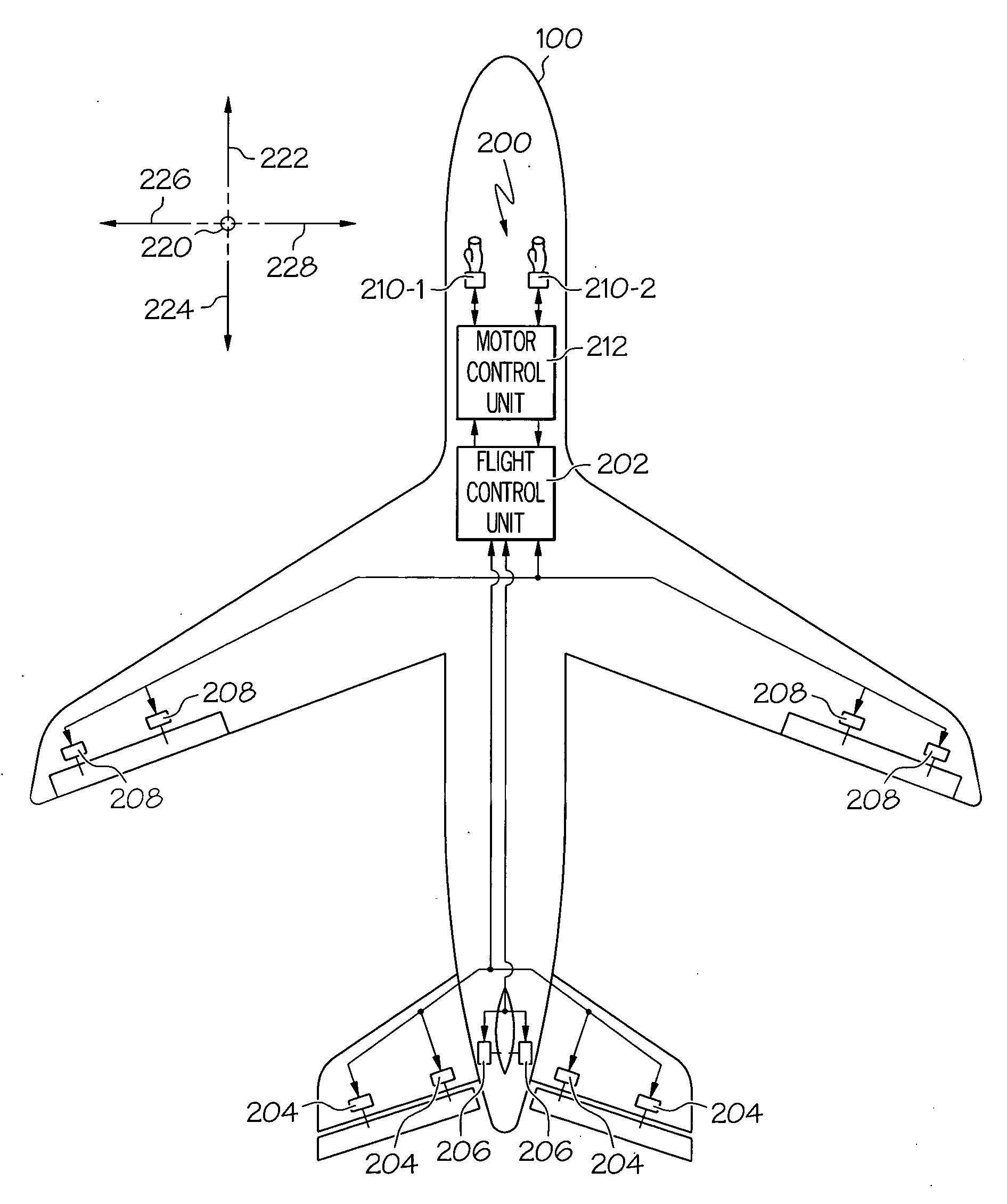
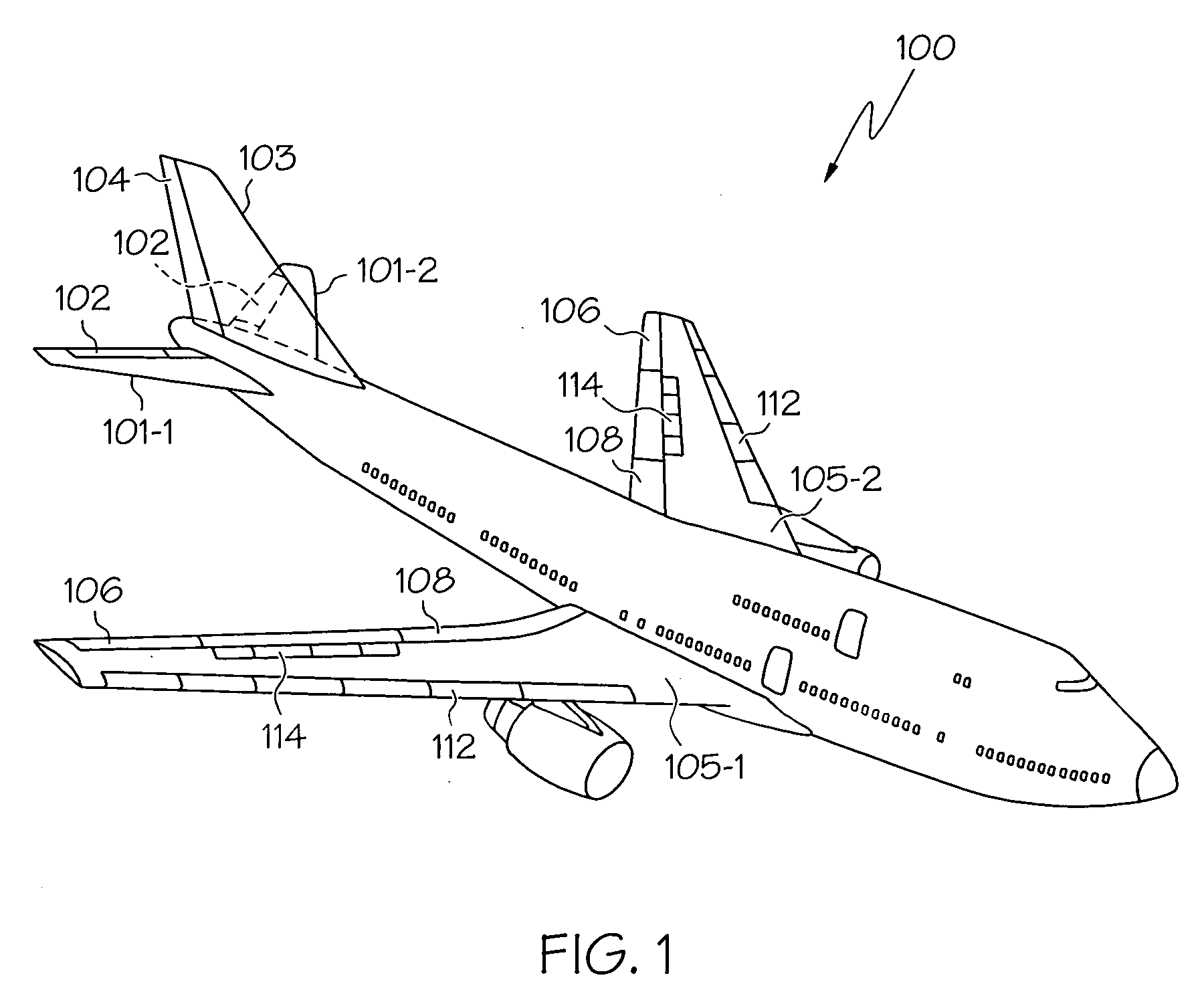
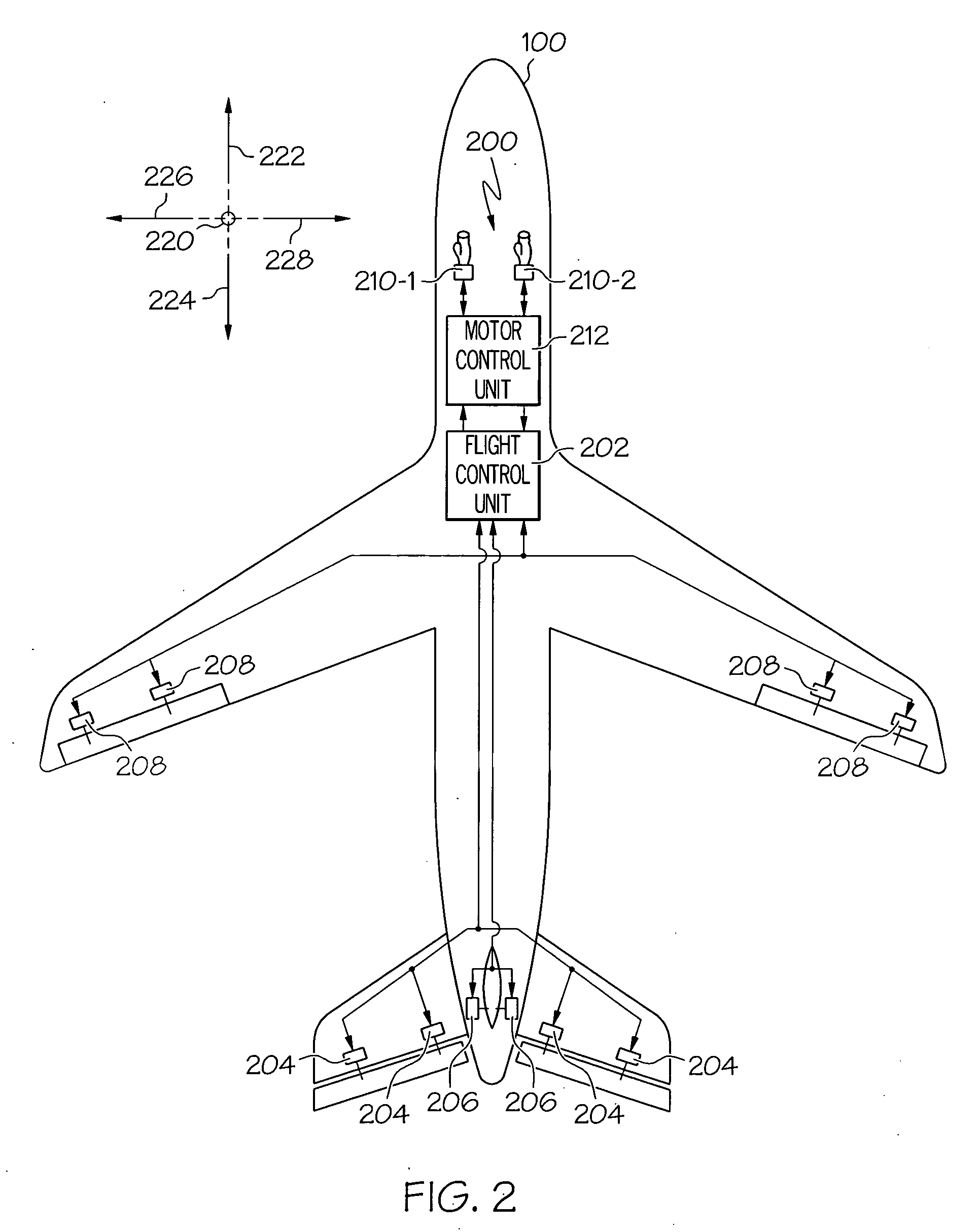
[0020]Turning first to FIG. 1, a perspective view of an exemplary aircraft is shown. In the illustrated embodiment, the aircraft 100 includes first and second horizontal stabilizers 101-1 and 101-2, respectively, a vertical stabilizer 103, and first and second wings 105-1 and 105-2, respectively. An elevator 102 is disposed on each horizontal stabilizer 101-1, 101-2, a rudder 104 is disposed on the vertical stabilizer 103, and an aileron 106 is disposed on each wing 105-1, 105-2. In addition, a plurality of flaps 108, slats 112, and spoilers 114 are disposed on each wing 105-1, 105-2. The elevators 102, the rudder 104, and the ailerons 106 a...


PUM


Abstract

A pilot flight control stick haptic feedback mechanism provides variable force feedback to the pilot flight control stick. The flight control stick is movable to a control position in a displacement direction. A motor control unit is operable to selectively supply motor feedback signals to a motor that is coupled to the flight control stick. The motor is responsive to the motor feedback signals to supply a variable feedback force to the flight control stick in a direction that opposes the displacement direction. A passive electromagnetic damping mechanism is electrically coupled to the motor and is at least selectively and passively supplies a non-braking damping force to the flight control stick.

Description

TECHNICAL FIELD[0001]The present invention relates to flight control sticks and, more particularly, to a pilot flight control stick feedback system that supplies haptic feedback to the pilot.BACKGROUND[0002]Aircraft typically include a plurality of flight control surfaces that, when controllably positioned, guide the movement of the aircraft from one destination to another. The number and type of flight control surfaces included in an aircraft may vary, but typically include both primary flight control surfaces and secondary flight control surfaces. The primary flight control surfaces are those that are used to control aircraft movement in the pitch, yaw, and roll axes, and the secondary flight control surfaces are those that are used to influence the lift or drag (or both) of the aircraft. Although some aircraft may include additional control surfaces, the primary flight control surfaces typically include a pair of elevators, a rudder, and a pair of ailerons, and the secondary flig...

Claims


Application Information

Patent Timeline
Patent Type & Authority Applications(United States)
IPC IPC(8): B64C13/46B64C13/04H02P23/04H02K21/00
CPCB64C13/503B64C13/46B64C13/507
Inventor HANLON, CASEYPOTTER, CALVIN C.WINGETT, PAUL T.WILKENS, DEAN R.ABEL, STEPHEN G.
Owner HONEYWELL INT INC
Why Eureka
Try Eureka