Developing Apparatus and Image Forming Apparatus that Incorporates the Developing Apparatus

a technology of developing apparatus and developing roller, which is applied in the direction of electrographic process apparatus, instruments, optics, etc., can solve the problems of uneven toner density in developed images, inability to reliably and inability to accurately supply to the toner supply roller and the developing roller

Active Publication Date: 2008-07-03
OKI ELECTRIC IND CO LTD
View PDF4 Cites 4 Cited by
  • Summary
  • Abstract
  • Description
  • Claims
  • Application Information

AI Technical Summary

Benefits of technology

[0008]An object of the invention is to provide a developing apparatus in which even if toner deteriorates due to convention in a large gap between a toner supplying roller and a developing roller, the toner adheres to the toner supplying roller without difficulty.

Problems solved by technology

If the toner in the developing apparatus has been deteriorated, a sufficient amount of the toner may not be supplied to a toner supplying roller and a developing roller reliably.
Deteriorated toner causes uneven toner density in developed images or causing light or vague images to be printed.
However, if a gap between the toner supplying roller and the developing roller is relatively large, the toner is subjected to convection in the gap so that the toner is difficult to adhere to the toner supplying roller or the toner adhering to the toner supplying roller may come off.

Method used


Image

  • Developing Apparatus and Image Forming Apparatus that Incorporates the Developing Apparatus
  • Developing Apparatus and Image Forming Apparatus that Incorporates the Developing Apparatus
  • Developing Apparatus and Image Forming Apparatus that Incorporates the Developing Apparatus

Examples


first embodiment

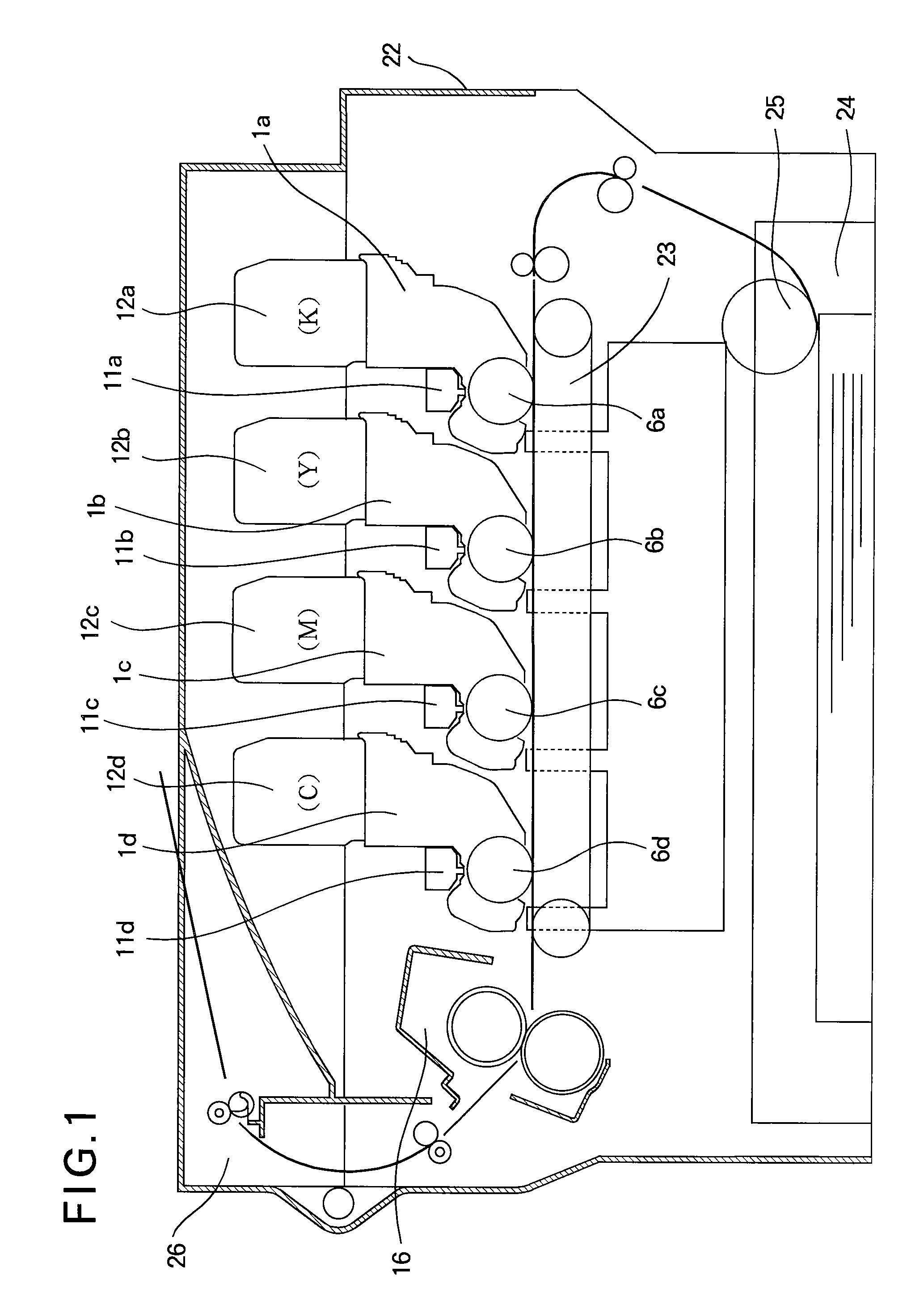
[0036]FIG. 1 illustrates the general configuration of an image forming apparatus 22 of a first embodiment. Developing apparatuses 1a-1d are detachably attached to the image forming apparatus 22, and form cyan magenta, yellow, and black images, respectively. Toner cartridges 12a-12d are detachably attached to the developing apparatus 1a-1d, respectively. Exposing units 11a-11d illuminate the charged surfaces of photoconductive drums 6a-6d in accordance with image data to form electrostatic latent images of corresponding colors. The electrostatic latent images formed by the exposing units 11a-11d are developed with toners of corresponding colors into toner images. A transfer belt unit 23 transports print medium 14 such as paper thereon, and transfers the toner images onto the print medium 14. A fixing unit 16 fixes the toner images of the respective colors into a permanent full color image. A paper cassette 24 holds a stack of print medium therein. A medium feeding section 25 feeds th...

second embodiment

[0068]The rib 17 of the first embodiment is formed in one piece with the toner reservoir 17. In contrast, a rib 18 of a second embodiment is formed as a piece separate from the toner reservoir 17. The description of elements similar to those of the first embodiment is omitted.

[0069]FIG. 8 is an expanded view illustrating the relation between a toner supplying roller 4 and toner 13 of the second embodiment. Elements similar to those of the first embodiment have been given the same reference numerals and their description is omitted. The only difference between the first embodiment and the second embodiment is that the rib 18 is a spacer-like piece separate from the toner reservoir 17.

[0070]Referring to FIG. 8, the toner 13 in the toner reservoir 17 adheres to the toner supplying roller 4 to form a toner layer 13a and a toner layer 13b. The toner layer 13a is formed upstream of the rib 18 with respect to rotation of the toner supplying roller 4, and the toner layer 13b is formed downs...

third embodiment

[0076]The first and second embodiments use the rib 170 in one piece with the toner reservoir 17 or the rib 18 integral with the toner reservoir 17. A third embodiment employs a rod 19 supported such that the rod 19 is not in contact with the inner wall surface of the toner reservoir 17. Description of elements similar to those of the first and second embodiments has been omitted.

[0077]FIG. 10 is an expanded view illustrating the relation between a toner supplying roller 4 and toner 13 of the third embodiment. Elements similar to those of the first embodiment (FIGS. 4 and 5) and the second embodiment (FIG. 8) have been given the same reference numerals and their description is omitted.

[0078]FIG. 11 is a side view illustrating the configuration and arrangement of the rod 19 in relation to the toner supplying roller 4 in the shape of a barrel. Elements shown in FIG. 11 similar to those shown in FIG. 7 have been given the same reference numerals and their description is omitted.

[0079]Th...


PUM


Abstract

A developing apparatus is incorporated in an image forming apparatus. An electrostatic latent image is formed on an image bearing body. A developing member supplies a developer material to the electrostatic latent image. A supplying member supplies the developer material to the developing member. A developer material chamber holds the developer material therein. A layer forming member is provide in the proximity to the supplying member, and forms a layer of the developer material. The layer forming member is positioned such that a gap Δg is defined between the layer forming member and the supplying member. When the supplying member rotates, the surface of the layer forming member applies pressure to the toner on the supplying member to form the layer having a smooth surface not more than 0.5 mm.

Description

BACKGROUND OF THE INVENTION[0001]1. Field of the Invention[0002]The present invention relates to a developing apparatus that supplies a developer material to a developing member and an image forming apparatus that incorporates the developing apparatus.[0003]2. Description of the Related Art[0004]Electrophotographic image forming apparatuses including printers, copying machines, and facsimile machines use electrophotographic technology. An exposing unit illuminates the uniformly charged surface of a photoconductive drum to form an electrostatic latent image. The electrostatic latent image is developed with toner into a toner image. The toner image is then transferred onto print paper. Subsequently, the toner image on the paper is fixed into a permanent image.[0005]If the toner in the developing apparatus has been deteriorated, a sufficient amount of the toner may not be supplied to a toner supplying roller and a developing roller reliably. Deteriorated toner causes uneven toner densi...

Claims


Application Information

Patent Timeline
Patent Type & Authority Applications(United States)
IPC IPC(8): G03G15/08
CPCG03G15/0812
Inventor KIKUCHI, KENJI
Owner OKI ELECTRIC IND CO LTD
Why Eureka
Try Eureka