Designation of Image Area

a technology of image area and design, applied in the field of image area design, can solve the problem that the transformation process cannot be performed, and achieve the effect of reducing the difficulty of transforming

Inactive Publication Date: 2009-03-12
SEIKO EPSON CORP
View PDF4 Cites 5 Cited by
  • Summary
  • Abstract
  • Description
  • Claims
  • Application Information

AI Technical Summary

Benefits of technology

[0009]An advantage of some aspects of the invention is that it provides a technique for designating an area of an image without difficulty in transforming an image of a specific kind of a photographic subject.

Problems solved by technology

Therefore, upon performing a process of transforming the contour of the facial image in an image corresponding to the designated area of the image, the transforming process cannot be performed when the area around the facial image is not included in the designated area.
Such a problem does not only occur in a process of transforming the facial image, but also occurs commonly in a process of designating an area of an image and transforming an image of a specific kind of a photographic subject corresponding to the designated area.

Method used


Image

  • Designation of Image Area
  • Designation of Image Area
  • Designation of Image Area

Examples


embodiment

A. Embodiment

A-1. Configuration of Image Processing Device

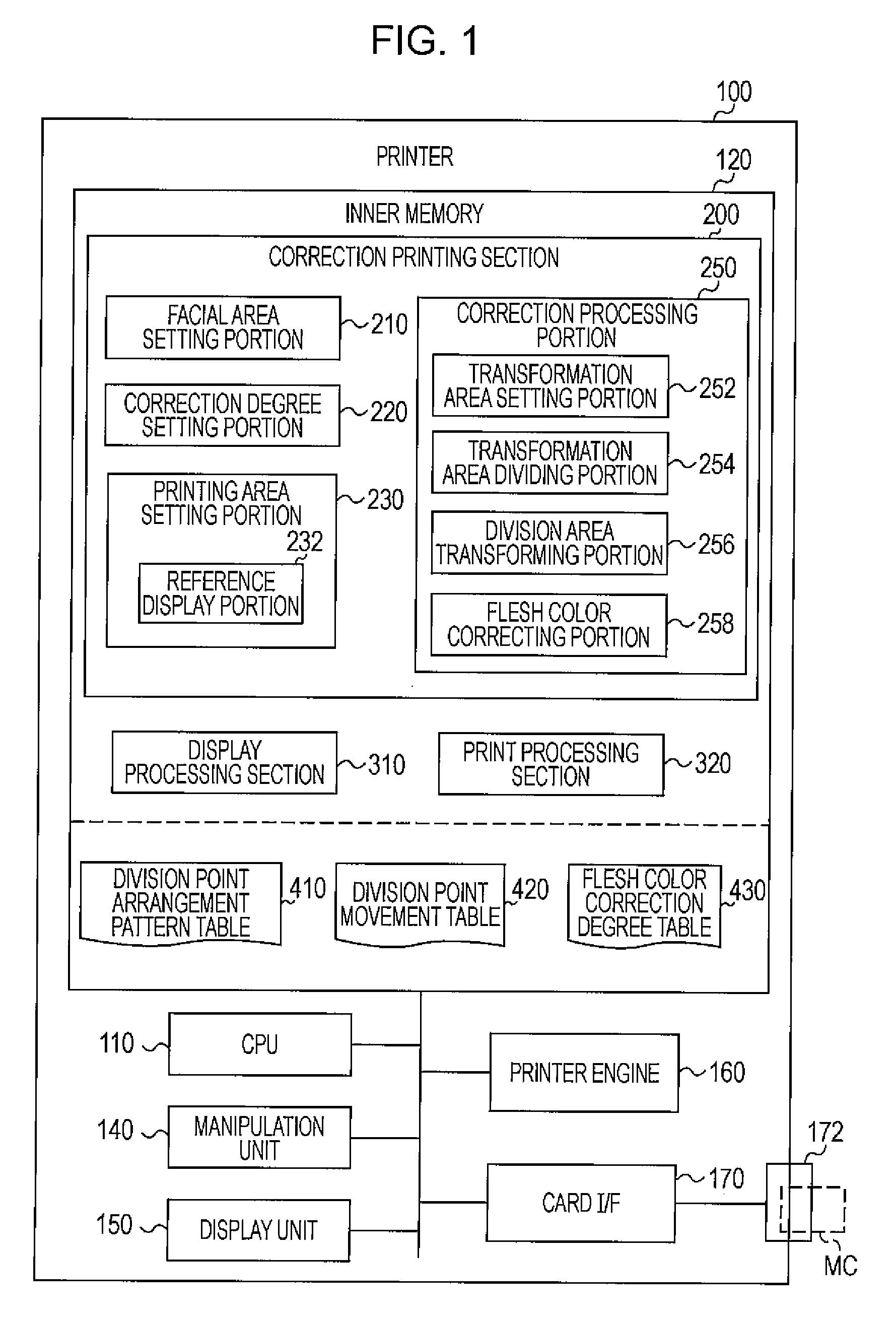
[0056]FIG. 1 is a schematic explanatory diagram of a printer 100 as an image processing device according to an embodiment of the invention. According to the embodiment, the printer 100 is a color inkjet printer corresponding to a so-called direct printer that prints an image on the basis of image data acquired from a memory card MC or the like. The printer 100 includes a CPU 110 that controls units of the printer 100, an inner memory 120 that includes a ROM, a RAM, and the like, a manipulation unit 140 that includes buttons or a touch panel, a display unit 150 that includes a liquid crystal display, a printer engine 160, and a card interface (card I / F) 170. The printer 100 may further include an interface that performs data communication with another device (for example, a digital still camera or a personal computer). The constituent elements of the printer 100 are connected to each other through buses.

[0057]The printer engin...

modified example 1

E1. Modified Example 1

[0127]FIG. 25 illustrates an example of a user interface used to set the printing area for face sheet FS in Modified Example 1. A difference from the example of FIG. 10 is that the reference frame RF is not shown in the display image DI and a transformation area frame TAF showing an area corresponding to the transformation area TA is displayed instead in Modified Example 1. In Modified Example 1, since the transformation area frame TAF is displayed in the display image DI, a user can set the printing area for the face sheet FS, which is set as the area of the target image TI corresponding to the trimming frame TF, as an area including the transformation area TA, by designating the trimming frame TF to include the transformation area frame TAF. Therefore, the face sheet image FI corresponding to the printing area for the face sheet FS includes an image area required to perform the face reduction correcting process. Accordingly, in Modified Example 1, it is also ...

modified example 2

B2. Modified Example 2

[0129]FIG. 26 illustrates an example of a user interface used to set the printing area for face sheet FS in Modified Example 2. A difference from the embodiment of FIG. 10 is that a facial area frame FAF showing an area corresponding to the facial area FA is also displayed on the display image DI in Modified Example 2. In Modified Example 2, the relationship between the reference frame RF and the trimming frame TF is different from that in the above-described embodiment. That is, when the reference frame RF is set to include the facial area frame FAF therein, the relationship between the reference frame RF and the trimming frame TF is set so that the trimming frame TF includes an area in the display image DI corresponding to the transformation area TA therein. Therefore, it is possible to set the printing area for the face sheet FS set as the area in the target image TI corresponding to the trimming frame TF in such a manner that the user designates the trimmin...


PUM


Abstract

An image processing device includes an image display unit that displays an image; an area designation receiving unit that receives designation of a first area in a display image by a user; a transformation processing unit that transforms an image corresponding to the first area in a predetermined transformation area in order to transform an image of a specific kind of photographic subject; and a reference display unit that shows a predetermined reference display in the display image in order to allow the user to designate an area, which includes a second area corresponding to the transformation area in the display image, as the first area.

Description

CROSS-REFERENCE TO RELATED APPLICATIONS[0001]This application claims the benefit of priority under 35 USC 119 of Japanese patent application no. 2007-235122, filed on Sep. 11, 2007, which is incorporated herein by reference.BACKGROUND[0002]1. Technical Field[0003]The invention relates to a technique for designating an area of an image.[0004]2. Related Art[0005]An image processing technique that transforms an image is known (for example, JP-A-2004-318204). JP-A-2004-318204 discloses an image processing technique capable of transforming a facial image by setting an area of the facial image (which shows a cheek image) in part as a correction area, dividing the correction area into plural small areas in accordance with a predetermined pattern, and enlarging or reducing the image at a ratio set in each of the small areas.[0006]Meanwhile, a process (a so-called trimming process) of designating an area of an image in part and trimming away an area other than the designated area or a proces...

Claims


Application Information

Patent Timeline
Patent Type & Authority Applications(United States)
IPC IPC(8): G06K9/34
CPCG06T11/60G06T3/0012
Inventor SHINGAI, KOSUKE
Owner SEIKO EPSON CORP
Why Eureka
Try Eureka