Refrigerating apparatus with turbo compressor

Inactive Publication Date: 2006-07-13
SAMSUNG ELECTRONICS CO LTD
View PDF14 Cites 18 Cited by
  • Summary
  • Abstract
  • Description
  • Claims
  • Application Information

AI Technical Summary

Benefits of technology

[0012] Accordingly, it is an aspect of the present invention to provide a refrigerating apparatus cooling a driving motor and a bearing member of a turbo compressor without difficulty.
[0013] It is another aspect of the present invention to provide a refrigerating apparatus restraining a refrigerant leaking between an impeller and a diffuser, and increasing efficiency of the turbo compressor.

Problems solved by technology

However, the conventional turbo compressor cannot efficiently cool down a plurality of bearing members provided on an outside of the driving motor by the introducing part and the discharging part.
Also, the conventional turbo compressor rotates the impeller with respect to the diffuser, thereby forming a gap between the impeller and the diffuser.

Method used


Image

  • Refrigerating apparatus with turbo compressor
  • Refrigerating apparatus with turbo compressor
  • Refrigerating apparatus with turbo compressor

Examples


first embodiment

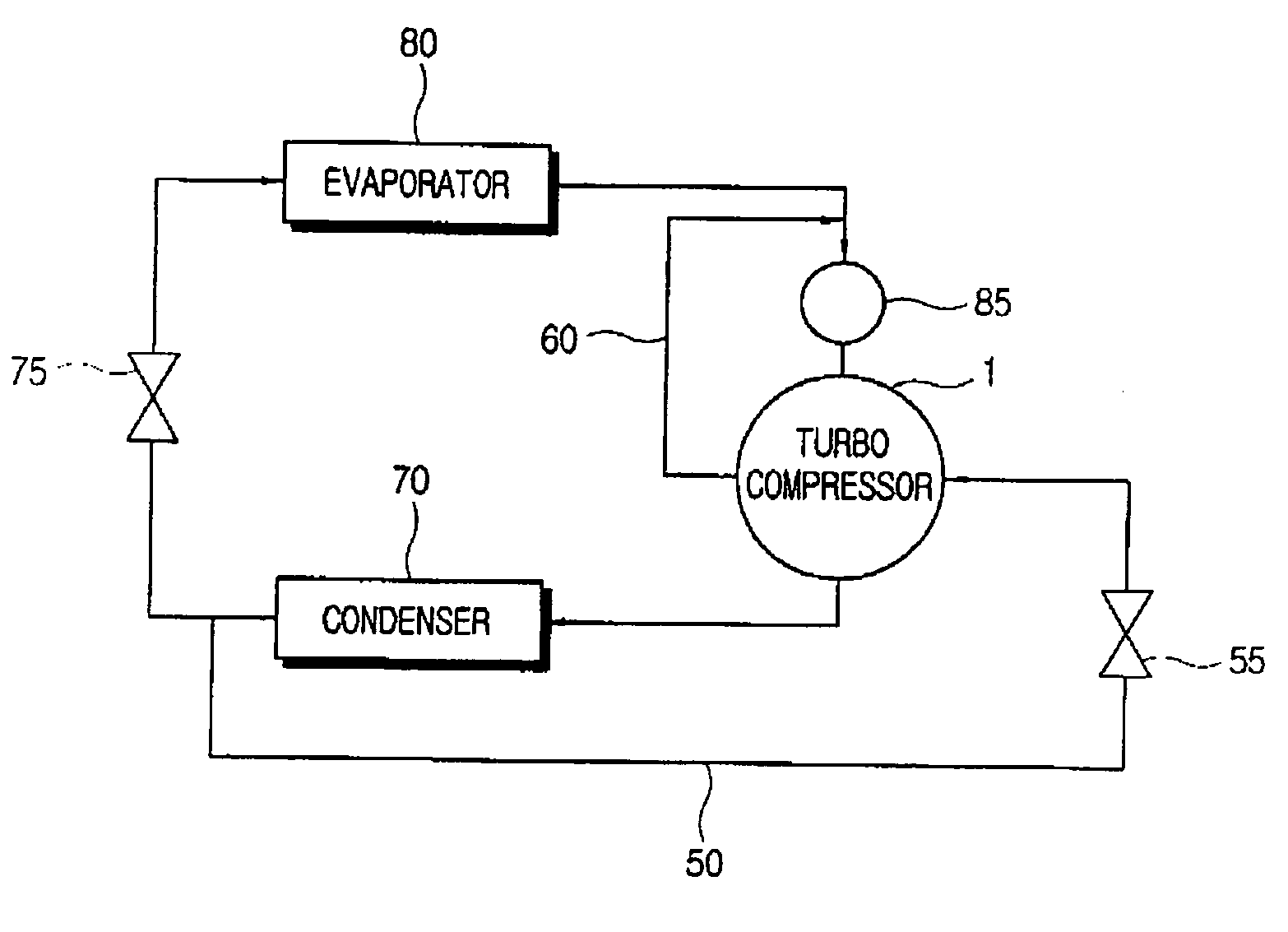
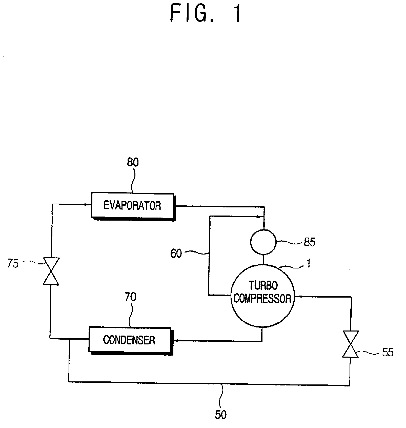
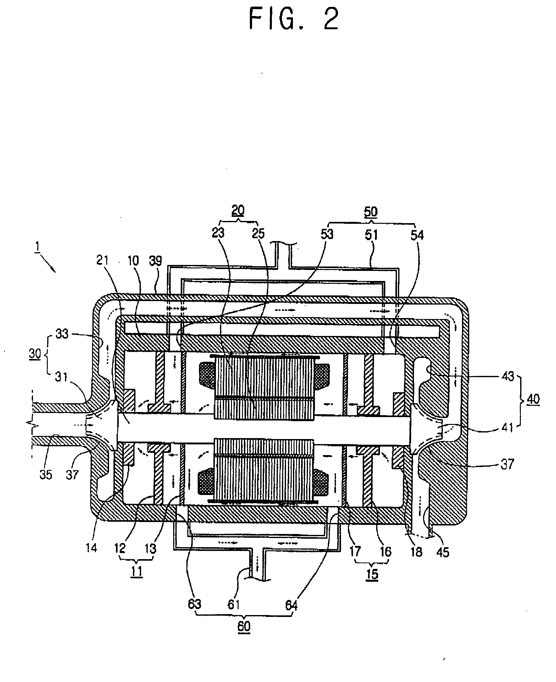
[0031] As shown in FIGS. 1 and 2, a refrigerating apparatus includes a turbo compressor 1 including a driving motor 20 and a plurality of bearing members 11 and 15 supporting a rotation axis 21 of the driving motor 20; a condenser 70 condensing a refrigerant gas compressed from the turbo compressor 1; a refrigerant supplying part 50 supplying a part of the refrigerant discharged from an outlet of the condenser 70 to the turbo compressor 1 to cool down the driving motor 20 and the bearing members 11 and 15; and a refrigerant discharging part 60 discharging a cooling refrigerant supplied by the refrigerant supplying part 50 and passing through the turbo compressor 1. The refrigerating apparatus according to the first embodiment of the present invention further includes an expansion unit 75 converting the refrigerant liquefied through the turbo compressor 1 and the condenser 70 into low temperature and low pressure; an evaporator 80 evaporating the refrigerant transmitted from the expa...

second embodiment

[0057] As shown in FIG. 3, a refrigerating apparatus according to a second embodiment of the present invention is differentiated from the first embodiment in that the refrigerating apparatus according to the second embodiment includes a first refrigerant connecting part 150 provided to mix a part of the refrigerant discharged from an outlet of the condenser 70 with the cooling refrigerant discharged from the refrigerant discharging part 60; and a second refrigerant connecting part 160 supplying the cooling refrigerant mixed by the first refrigerant connecting part 150 to a turbo compressor 101 to be mixed with refrigerant gas compressed once by the first compressing part 30. In the second embodiment of the present invention, the cooling refrigerant discharged from the refrigerant discharging part 60 is mixed with the cooling refrigerant supplied from the first refrigerant connecting part 150 to lower temperature, and then supplied to the refrigerant gas moving part 39 provided betwe...


PUM


Abstract

A refrigerating apparatus, including a turbo compressor including a driving motor and a plurality of bearing members supporting a rotation axis of the driving motor; a condenser provided to condense a refrigerant gas compressed from the turbo compressor; a refrigerant supplying part supplying a part of a refrigerant discharged from an outlet of the condenser to the turbo compressor to cool down the driving motor and the bearing members; and a refrigerant discharging part provided to discharge a cooling refrigerant supplied by the refrigerant supplying part and passing through the turbo compressor. Thus, the refrigerating apparatus cools a driving motor and a bearing member of a turbo compressor without difficulty. Also, the refrigerating apparatus restrains a refrigerant from leaking between an impeller and a diffuser, and increases the efficiency of the turbo compressor.

Description

CROSS-REFERENCE TO RELATED APPLICATIONS [0001] This application claims the benefit of Korean Patent Application No. 2005-0002201, filed on Jan. 10, 2005, in the Korean Intellectual Property Office, the disclosure of which is incorporated herein by reference. BACKGROUND OF THE INVENTION [0002] 1. Field of the Invention [0003] The present invention relates to a refrigerating apparatus with a turbo compressor, and more particularly, to a refrigerating apparatus having an improved structure to efficiently cool a driving motor of a turbo compressor and a bearing member supporting a rotation axis of the driving motor. [0004] 2. Description of the Related Art [0005] Generally, a refrigerating apparatus includes a compressor for compressing a gaseous in order to raise the temperature and pressure of the refrigerant; a condenser to condense the gaseous refrigerant compressed in the compressor into a liquid refrigerant; an expansion unit such as a capillary tube or an expansion valve to lower...

Claims


Application Information

Patent Timeline
IPC IPC(8): F25B1/00F25B1/10
CPCF04D29/05F04D29/584F25B1/053F25B31/006F25B2400/13F04D25/06F04D29/056F04D29/5806H02K9/02F05D2210/12Y10S415/00Y10S417/00
Inventor RO, SOO-HYUK
Owner SAMSUNG ELECTRONICS CO LTD
Why Eureka
Try Eureka