Cervical distraction device

a cervical distraction and cervical technology, applied in the field of implantable distraction devices, can solve the problems of reducing the foraminal area, radicular pain, pain and disability of a large segment of the population, and achieve the effects of reducing radicular symptoms, preserving the physiology of the spine, and increasing the foraminal dimension

a cervical distraction and cervical technology, applied in the field of implantable distraction devices, can solve the problems of reducing the foraminal area, radicular pain, pain and disability of a large segment of the population, and achieve the effects of reducing radicular symptoms, preserving the physiology of the spine, and increasing the foraminal dimension

US20080161929A1Inactive Publication Date: 2008-07-03PROVIDENCE MEDICAL TECH

Image

  • Cervical distraction device
  • Cervical distraction device
  • Cervical distraction device

Examples


Embodiment Construction

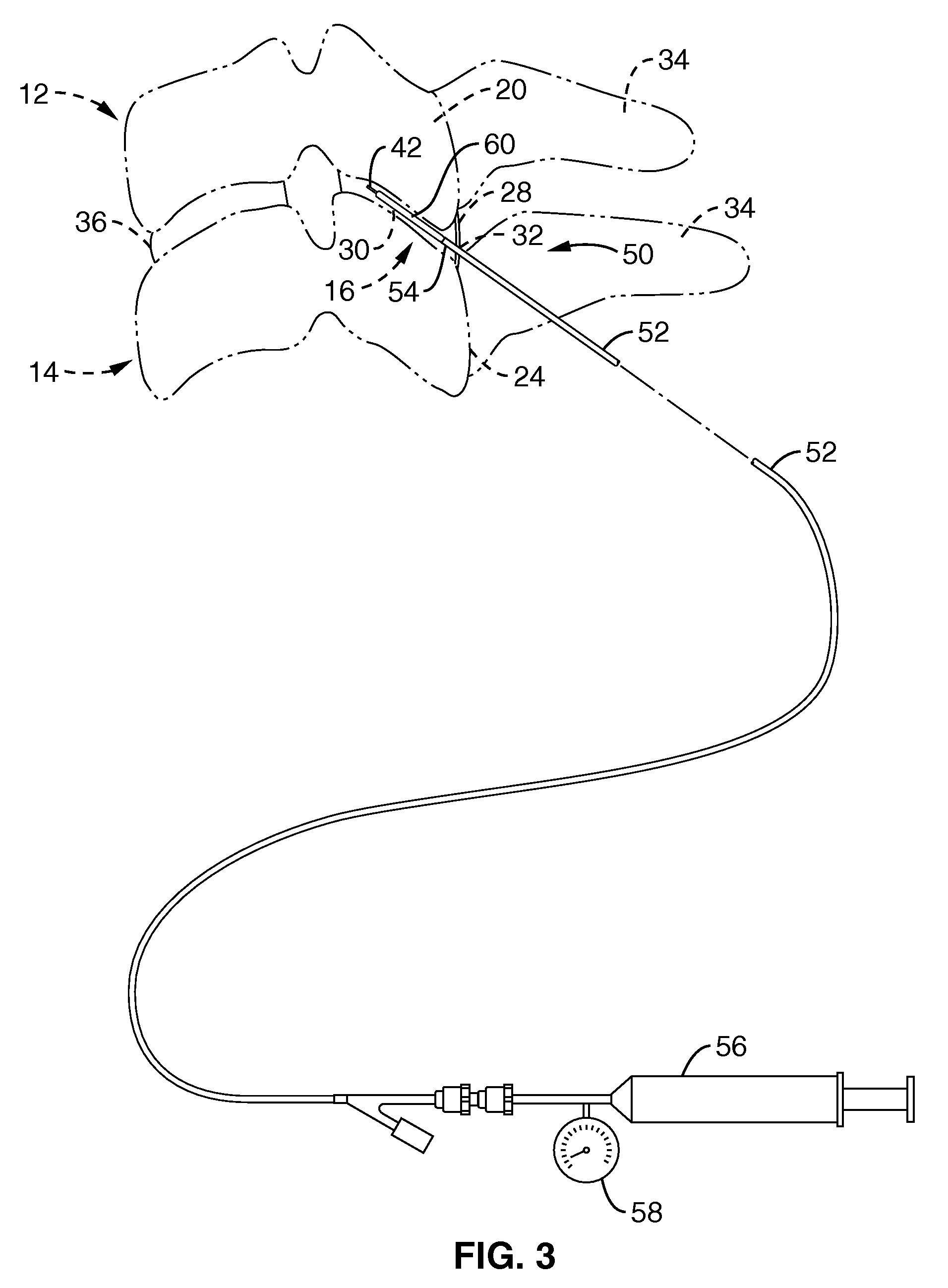
[0047]Referring more specifically to the drawings, for illustrative purposes the present invention is embodied in the apparatus generally shown in FIG. 2 through FIG. 13. It will be appreciated that the apparatus may vary as to configuration and as to details of the parts, and that the method may vary as to the specific steps and sequence, without departing from the basic concepts as disclosed herein.

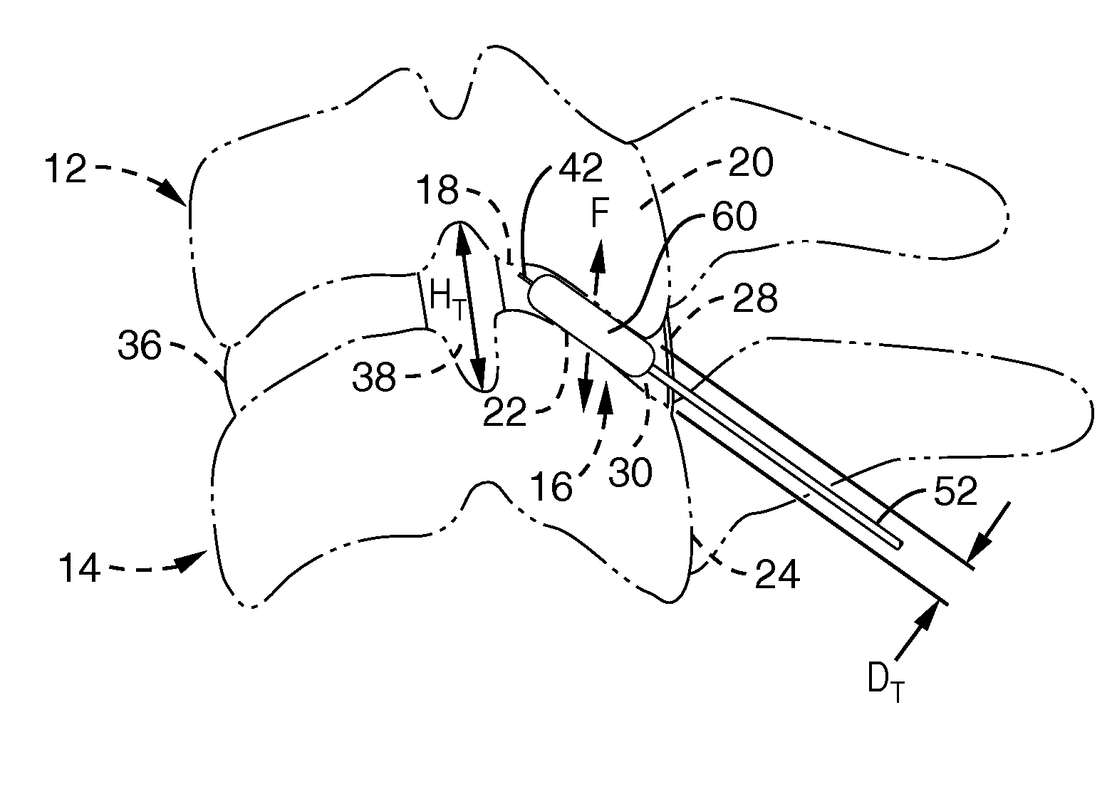
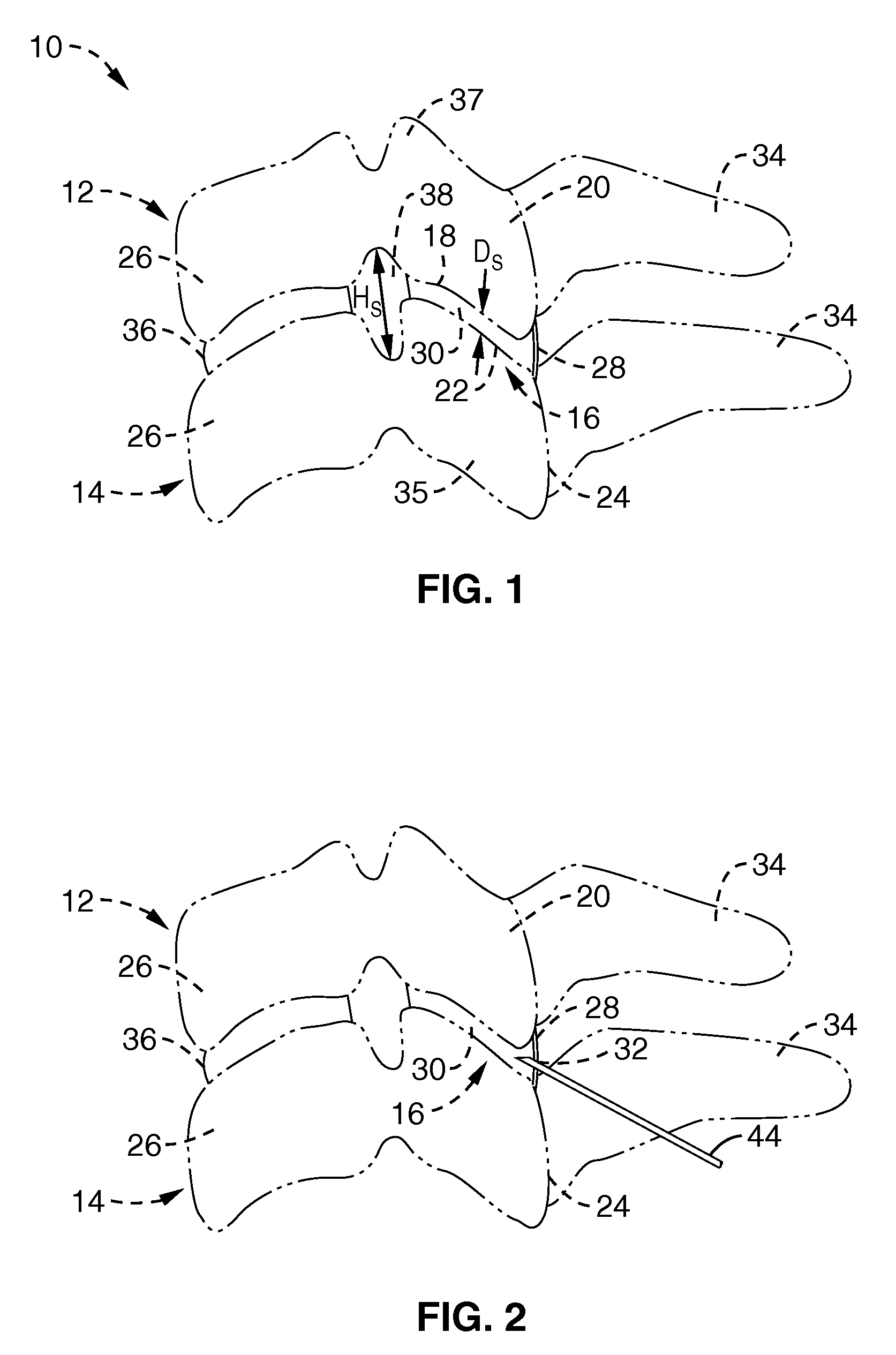
[0048]FIG. 1 illustrates a simplified lateral view of a portion of the cervical spine 10. The basic biomechanical unit or motion segment of the spine consists of two adjacent vertebrae 12 and 14 and the three joint articular complex through which they move and are constrained in relation to one another. The spine articulations generally consist of an intervertebral disc 26 located between the vertebral bodies 26 of adjacent vertebrae 12, 14, and two facet joints 16 symmetrically located laterally from the sagittal plane at the posterior end of the vertebral bodies 26.

[0049]The facet joi...


PUM

PropertyMeasurementUnit
widthaaaaaaaaaa
depthaaaaaaaaaa
widthaaaaaaaaaa

Abstract

A device and method for a minimally invasive surgical implantation to reduce radicular symptoms by inserting an expandable cervical distraction implant in the facet joint and distracting the adjacent cervical vertebrae to increase the foraminal dimension. The implant, when positioned in the cervical facet joint, expands to via delivery of an inflation medium to increase the space between the vertebrae, thereby increasing the foraminal area or dimension, and reducing pressure on the nerves and blood vessels of the cervical spine.

Description

CROSS-REFERENCE TO RELATED APPLICATIONS[0001]Not ApplicableSTATEMENT REGARDING FEDERALLY SPONSORED RESEARCH OR DEVELOPMENT[0002]Not ApplicableINCORPORATION-BY-REFERENCE OF MATERIAL SUBMITTED ON A COMPACT DISC[0003]Not ApplicableNOTICE OF MATERIAL SUBJECT TO COPYRIGHT PROTECTION[0004]A portion of the material in this patent document is subject to copyright protection under the copyright laws of the United States and of other countries. The owner of the copyright rights has no objection to the facsimile reproduction by anyone of the patent document or the patent disclosure, as it appears in the United States Patent and Trademark Office publicly available file or records, but otherwise reserves all copyright rights whatsoever. The copyright owner does not hereby waive any of its rights to have this patent document maintained in secrecy, including without limitation its rights pursuant to 37 C.F.R. § 1.14.BACKGROUND OF THE INVENTION[0005]1. Field of the Invention[0006]This invention per...

Claims


Application Information

Patent Timeline
03 Jul 2008
Publication
US20080161929A1
IPC
A61F2/44
CPC
A61F2/441; A61F2/4405; A61B17/562; A61B17/7064; A61B2017/681; A61F2/4611
Inventors
MCCORMACK, BRUCE; SMITH, JEFF