Method and system of feeding cable through an enclosure while maintaining electrognetic shielding

a technology of electrognetic shielding and enclosure, which is applied in the direction of coupling device details, coupling device connection, aperture leaage reduction, etc., can solve the problems of affecting the effective performance of those other circuits

Inactive Publication Date: 2008-07-10
IBM CORP
View PDF5 Cites 22 Cited by
  • Summary
  • Abstract
  • Description
  • Claims
  • Application Information

AI Technical Summary

Benefits of technology

[0007]An exemplary embodiment disclosed herein relates to a method of feeding cable through a wall. The method includes, cutting an outer jacket of a cable, and pulling the outer jacket away from the cut thereby exposing an electromagnetic interference shielding layer. The method further includes, clamping a conductor around the shielding layer, securing the clamped conductor to a conductive wall, and electrically connecting the clamped conductor to the conductive wall.
[0008]Further disclosed herein is an embodiment of a method of electr

Problems solved by technology

Electromagnetic Interference or EMI is electromagnetic radiation which is emitted by electrical circuits carrying rapidly changing signals, as a by-product of their normal operation, and which causes unwanted signals (interference or noise) to be induced in other c

Method used


Image

  • Method and system of feeding cable through an enclosure while maintaining electrognetic shielding
  • Method and system of feeding cable through an enclosure while maintaining electrognetic shielding
  • Method and system of feeding cable through an enclosure while maintaining electrognetic shielding

Examples


Embodiment Construction

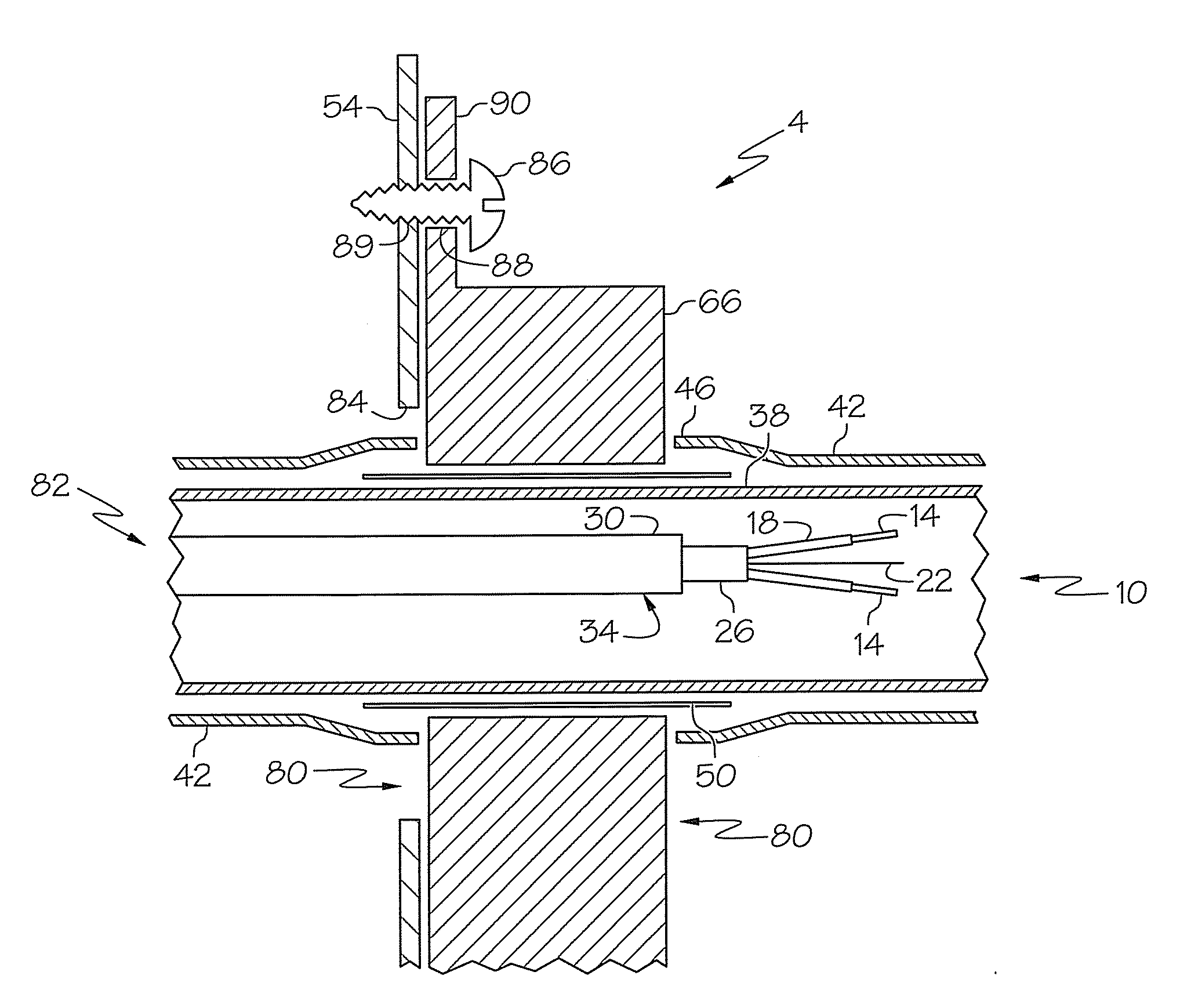
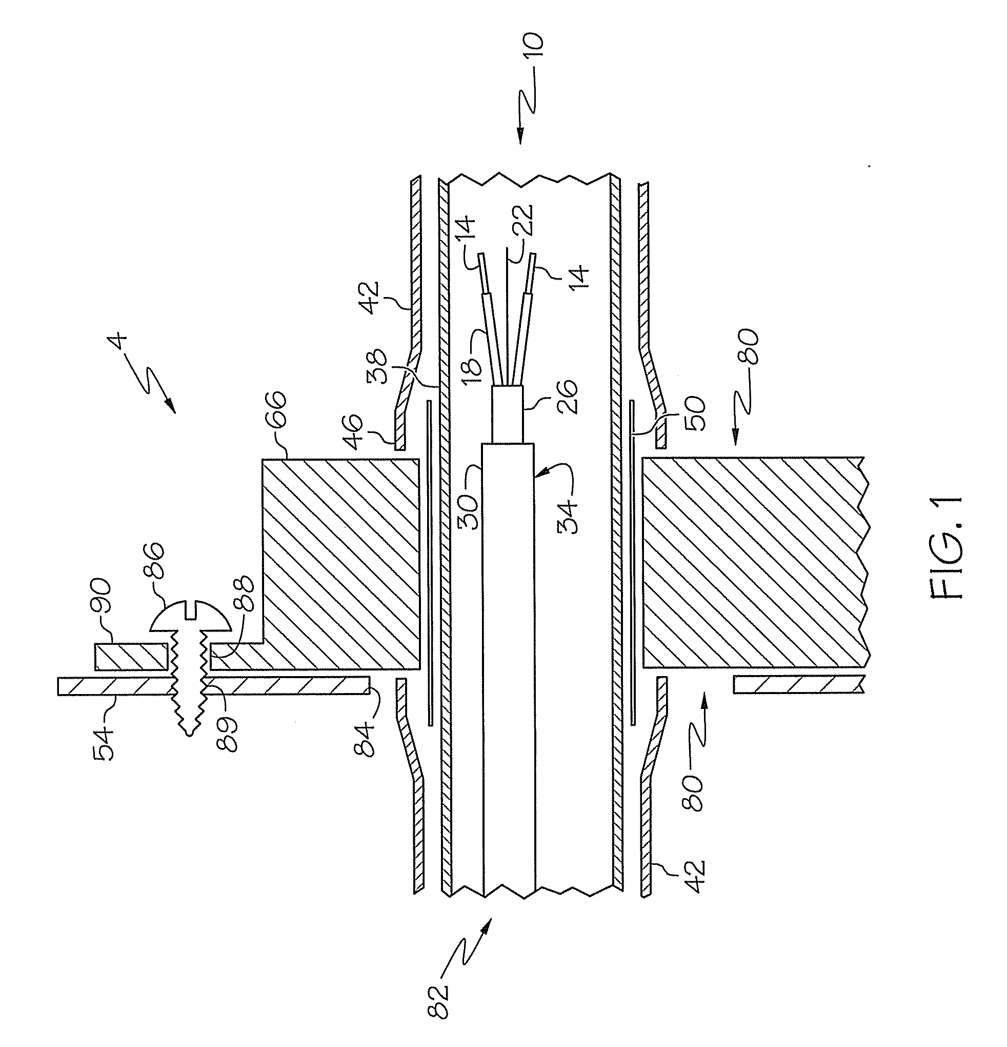
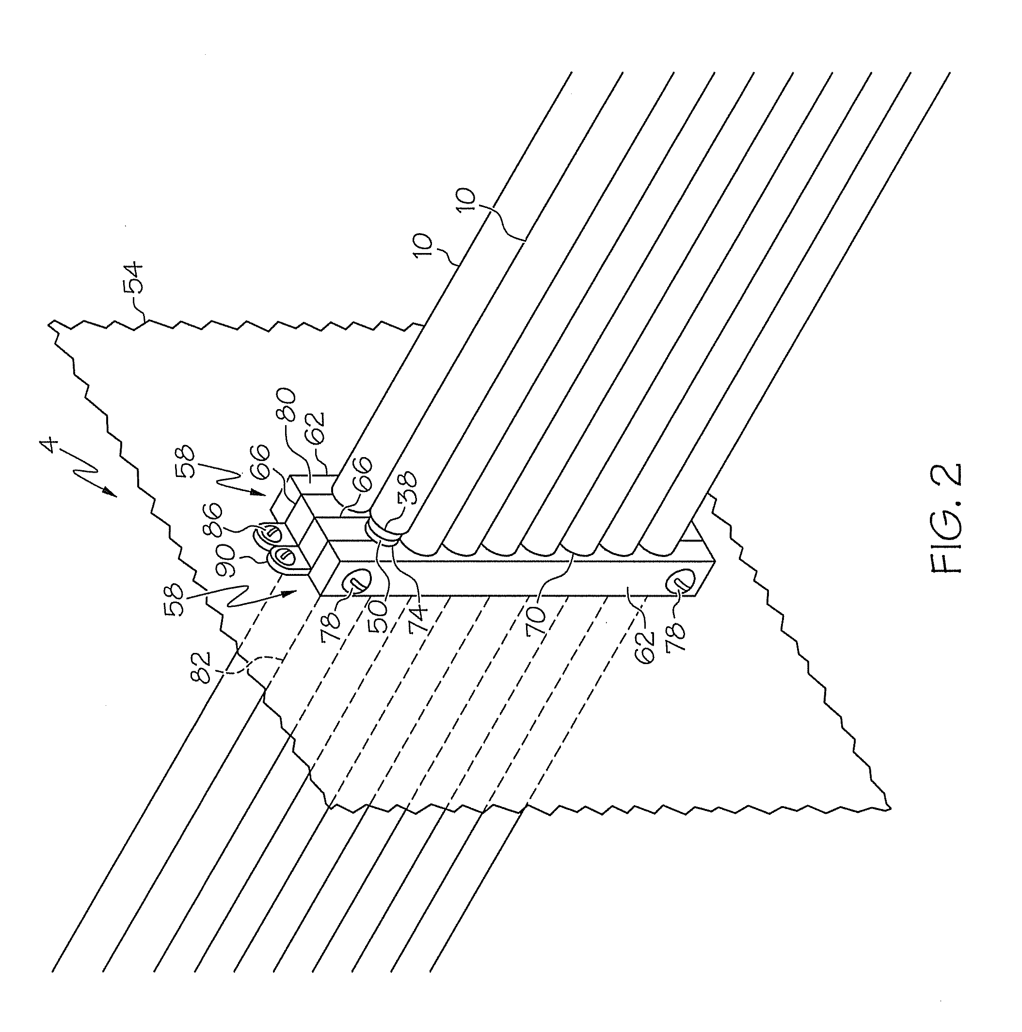
[0013]A detailed description of several embodiments of the disclosed apparatus and method are presented herein by way of exemplification and not limitation with reference to the Figures.

[0014]Referring to FIG. 1 an exemplary embodiment disclosed herein of a cable to enclosure interface system is shown generally at 4. A cable 10 includes a plurality of signal conductors 14 each with insulation 18 thereon. A ground wire 22 is coupled with a pair of signal conductors 14 and is encased by a signal shield 26 and a jacket 30 comprising a shielded pair 34. A cable shield 38 and an outer jacket 42 encircle a plurality of shielded pairs 34 (only one pair is shown) to complete the construction of the cable 10. Alternate cable constructions with an outer jacket and EMI shielding layer could also be employed within the scope and spirit of the present invention.

[0015]The cable shield 38 minimizes EMI from escaping from the cable 10 or intruding into the cable 10 where it could interfere with the...


PUM


Abstract

An exemplary embodiment disclosed herein relates to a method of feeding cable through a wall. The method includes, cutting an outer jacket of a cable, and pulling the outer jacket away from the cut thereby exposing an electromagnetic interference shielding layer. The method further includes, clamping a conductor around the shielding layer, securing the clamped conductor to a conductive wall, and electrically connecting the clamped conductor to the conductive wall.

Description

GOVERNMENT INTEREST[0001]This invention was made with Government support under contract No.: B517552 awarded by The Department of Energy. The Government has certain rights in this invention.[0002]IBM ® is a registered trademark of International Business Machines Corporation, Armonk, N.Y., U.S.A. Other names used herein may be registered trademarks, trademarks or product names of International Business Machines Corporation or other companiesBACKGROUND OF THE INVENTION[0003]Electromagnetic Interference or EMI is electromagnetic radiation which is emitted by electrical circuits carrying rapidly changing signals, as a by-product of their normal operation, and which causes unwanted signals (interference or noise) to be induced in other circuits. This interrupts, obstructs, or otherwise degrades or limits the effective performance of those other circuits. Electromagnetic Interference is also known as Radio Frequency Interference or RFI.[0004]Most countries have legal requirements that ele...

Claims


Application Information

Patent Timeline
IPC IPC(8): H05K9/00H02G3/22
CPCH05K9/0018H02G3/22
Inventor CIPOLLA, THOMAS M.
Owner IBM CORP
Why Eureka
Try Eureka