Apparatus for closing a curved anvil of a surgical stapling device

a stapling device and curved technology, applied in the field of surgical staplers, can solve the problems of difficult surgeon positioning the jaw of the end-effector behind, the surgeon may not be able to see the distal end of the end-effector, and the end-effector having such a linear configuration is somewhat difficult to us

Active Publication Date: 2008-07-17
CILAG GMBH INT
View PDF99 Cites 347 Cited by
  • Summary
  • Abstract
  • Description
  • Claims
  • Application Information

AI Technical Summary

Benefits of technology

[0111]an anvil configured to deform the staples, said anvil having a proximal portion, a distal portion, and a middle portion intermediate said proximal portion and said distal portion, wherein said anvil is movable between a first position and a second position, wherein said anvil and the staple cartridge are configured to hold said tissue therebetween when said anvil is in said second position, and wherein said proximal portion and said distal portion of said anvil are closer to the staple cartridge than said middle portion when said anvil is in said second position.

Problems solved by technology

However, in some circumstances, end-effectors having such a linear configuration are somewhat difficult to use.
More particularly, for example, when the end-effector must be placed adjacent to or against a cavity wall, such as the thoracic cavity wall, for example, it is often difficult for the surgeon to position a jaw of the end effector behind delicate or fragile tissue which is proximal to and / or attached to the cavity wall.
Furthermore, even if the surgeon is successful in positioning a jaw behind the tissue, owing to the linear configuration of the end-effector, the surgeon may not be able to see the distal end of the end-effector.
However, owing to the amount of force that is typically transmitted through the flexible drive member, the drive member may buckle or otherwise deform in an unsuitable manner.

Method used


Image

  • Apparatus for closing a curved anvil of a surgical stapling device
  • Apparatus for closing a curved anvil of a surgical stapling device
  • Apparatus for closing a curved anvil of a surgical stapling device

Examples


Embodiment Construction

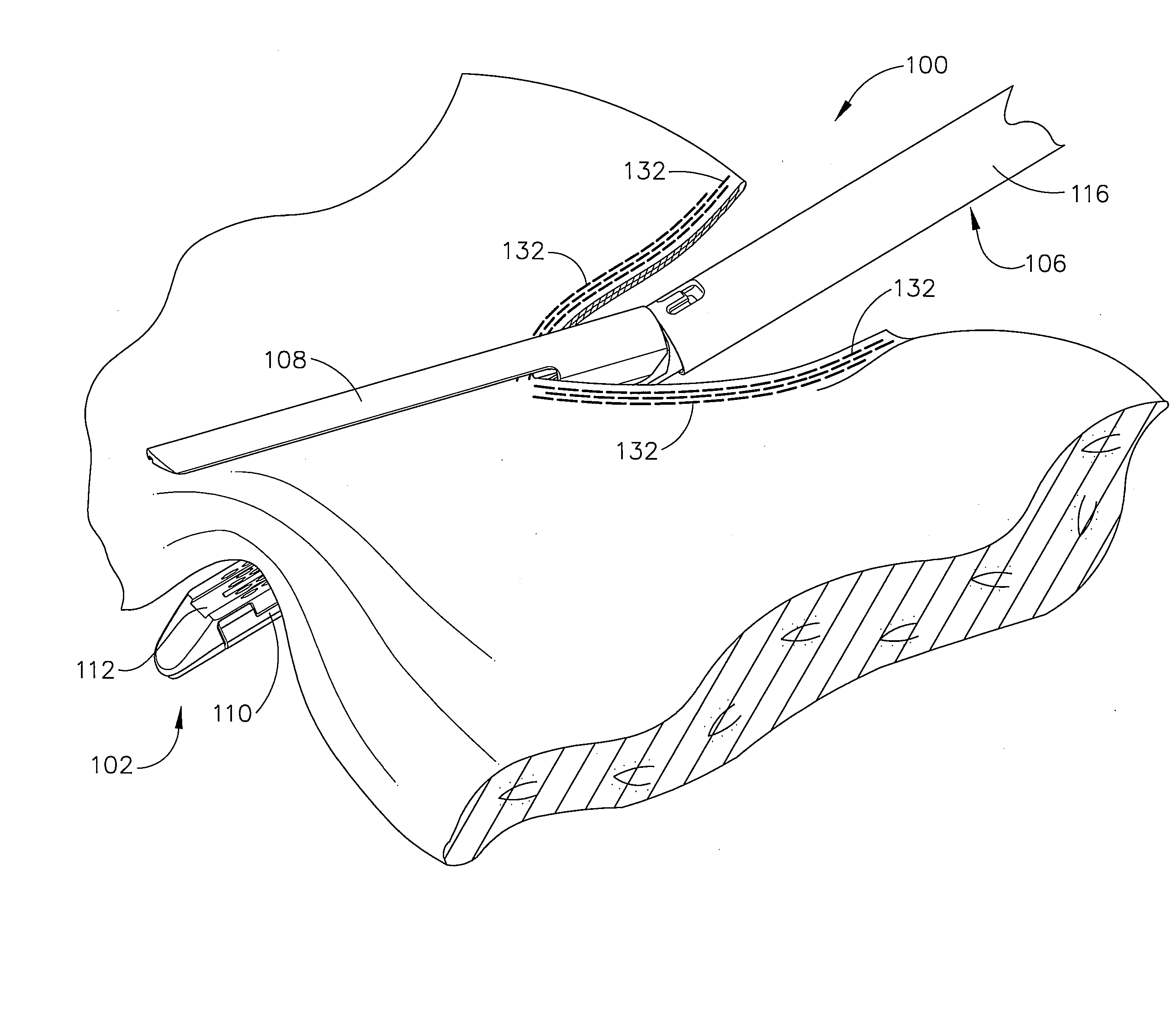
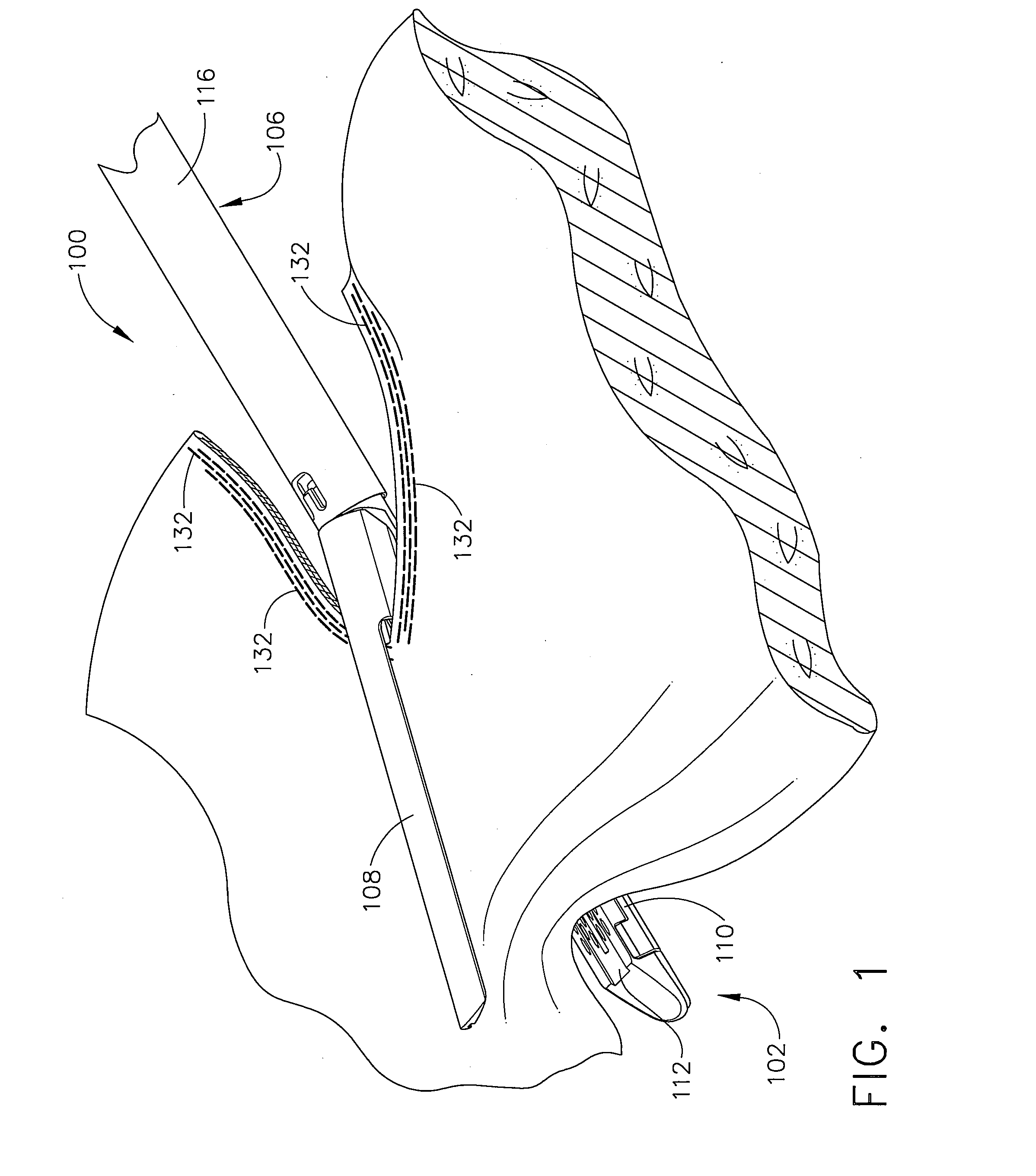
[0067]As known in the art, it is often necessary to resect tissue from a patient after the tissue has become necrotic or cancerous, for example. Frequently, blood vessels within the tissue are transected as the tissue is being cut. As a result, blood may flow from the blood vessels and complicate the surgery or endanger the patient. Often, a surgical stapler is used to secure and compress several layers of tissue together in order to substantially close the blood vessels. For example, referring to FIG. 1, a surgical stapler, such as an endocutter, can include devices which staple and then cut the tissue. As a result, the blood vessels can be substantially closed by the staples before the tissue is cut, thereby reducing bleeding therefrom.

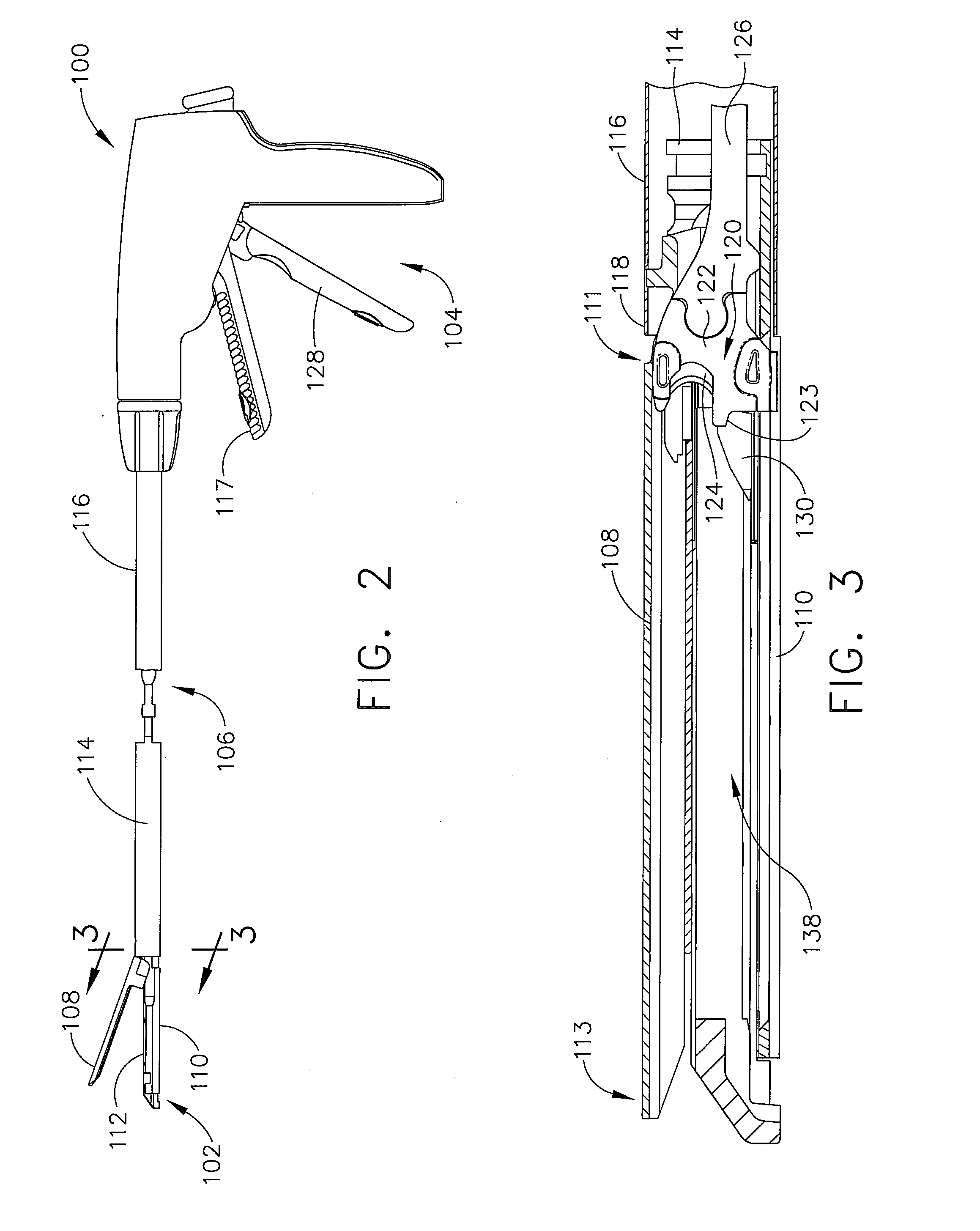
[0068]Referring to FIGS. 1 and 2, endocutters, such as endocutter 100, for example, typically include an end-effector 102, a handle portion 104 (FIG. 2), and a shaft 106 extending therebetween. End-effector 102 includes first jaw 108 and second jaw ...


PUM

PropertyMeasurementUnit
angleaaaaaaaaaa
angleaaaaaaaaaa
angleaaaaaaaaaa

Abstract

The present invention includes a surgical stapler having a staple cartridge, an anvil, and a cutting member having a cutting surface, wherein the cutting member is relatively movable with respect to the anvil and the staple cartridge. In at least one embodiment, the anvil is movable between an open position and a partially-closed position. When the anvil is in its partially-closed position, the anvil and the staple cartridge can be configured to capture tissue therebetween without fully compressing the tissue. In at least one embodiment, the anvil includes a proximal portion, a distal portion, and a middle portion intermediate the proximal portion and the distal portion. In these embodiments, the tissue can be captured between the proximal and distal portions of the anvil before the middle portion of the anvil is brought into contact with the tissue.

Description

CROSS REFERENCE TO RELATED APPLICATIONS[0001]The subject application is related to six co-pending and commonly-owned applications filed on even date herewith, the disclosure of each is hereby incorporated by reference in their entirety, these six applications being respectively entitled:[0002](1) Surgical Stapling Device With a Curved Cutting Member to Frederick E. Shelton, IV, and Jerome R. Morgan (K&LNG Docket No. 060333 / END5918USNP);[0003](2) Surgical Stapling Device Having Supports for a Flexible Drive Mechanism to Frederick E. Shelton, IV, and Jerome R. Morgan (K&LNG Docket No. 060334 / END5919USNP);[0004](3) Surgical Stapling Device With a Curved End Effector to Frederick E. Shelton, IV, Jerome R. Morgan, and Stephen J. Balek (K&LNG Docket No. 060349 / END5929USNP);[0005](4) Improved Curved End Effector for a Surgical Stapling Device to Frederick E. Shelton, IV, Jerome R. Morgan, Stephen J. Balek, and Douglas Siebenaler (K&LNG Docket No. 060348 / END5930USNP);[0006](5) Improved Butt...

Claims


Application Information

Patent Timeline
Patent Type & Authority Applications(United States)
IPC IPC(8): A61B17/64
CPCA61B17/07207A61B2017/07214A61B2017/07221A61B2017/2945A61B2017/2936A61B2017/2944A61B2017/0725A61B2017/3456A61B17/07292A61B17/32A61B2017/07278A61B2017/07228A61B2017/320044A61B17/122A61B17/068A61B17/0686A61B2090/08021A61B17/105A61B17/320016A61B17/205
Inventor SHELTON, FREDERICK E.MORGAN, JEROME R.
Owner CILAG GMBH INT
Why Eureka
Try Eureka