Blind rivet

a blind rivet and rivet technology, applied in the field of blind rivets, can solve the problems of not being able to loosely set, loosely set, and generally not being able to under-torque, over-torque, etc., and achieve the effects of reducing the amount and cost of materials, minimizing the cost of production, use, and disposal of spent mandrels

Active Publication Date: 2008-07-17
TAYLOR HARRY E
View PDF65 Cites 23 Cited by
  • Summary
  • Abstract
  • Description
  • Claims
  • Application Information

AI Technical Summary

Benefits of technology

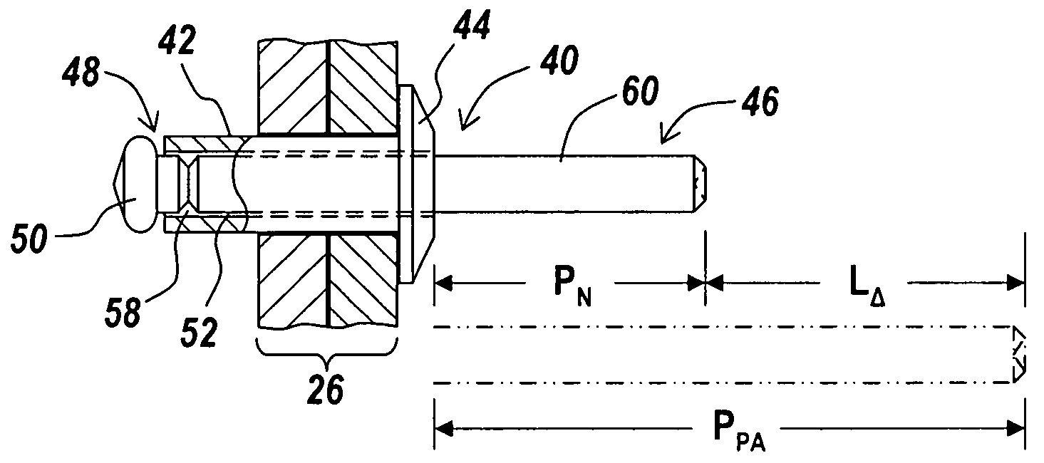
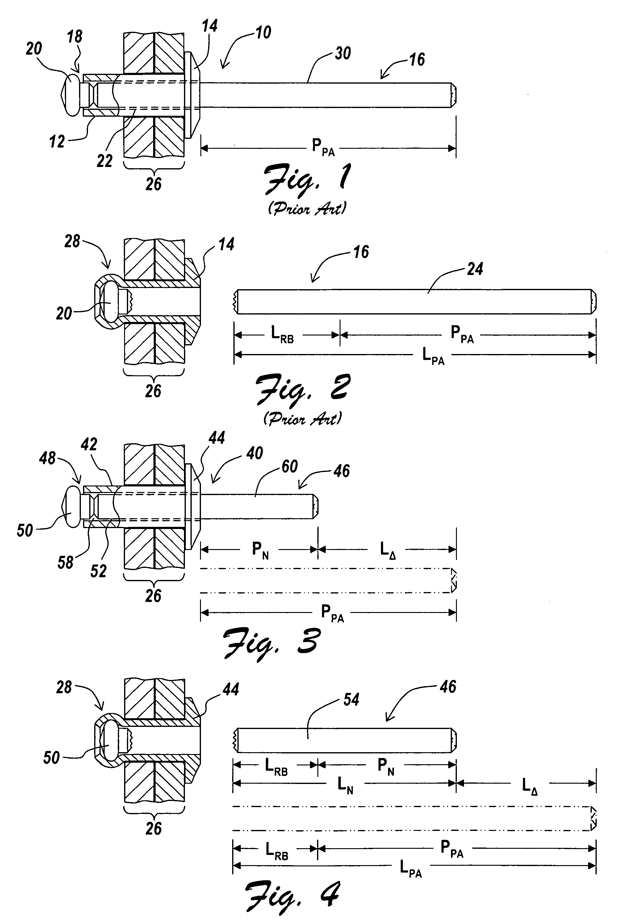
[0014]There is a need for a blind rivet design where the characteristics of the exposed mandrel portion are modified from the conventional mandrel to reduce amount and cost of materials required to produce the mandrel, while also minimizing costs related to production, use, and spent mandrel disposal, all while still making use of conventional riveting tools for rivet setting and maintaining rivet performance. The present invention is directed toward further solutions to address this need, in addition to having other desirable characteristics.

Problems solved by technology

Unlike many other fasteners, it is generally not possible to under-torque, over-torque, or loosely set a blind rivet since the clamping load is determined by a predetermined breaking load of the blind rivet mandrel.
There are costs associated with the mandrels both at the manufacturing end where the rivets are made, and at the user end where the rivets are installed and the spent mandrels need to be disposed of in some form or another.
At the user end, there are costs associated with collecting, storing, and disposing of the spent mandrels, especially at locations where there are large quantities of rivet usage.
However, because the IFI and others have standardized the exposed mandrel portion 30 length dimension PPA, there has been no recognition of this problem.
If there is too little surface area that can be gripped by the riveting tool, then problems can develop in setting the rivet, such as the jaws of the riveting tool slipping off the mandrel at the higher tensile loads required for break away.

Method used


Image

  • Blind rivet
  • Blind rivet
  • Blind rivet

Examples


Embodiment Construction

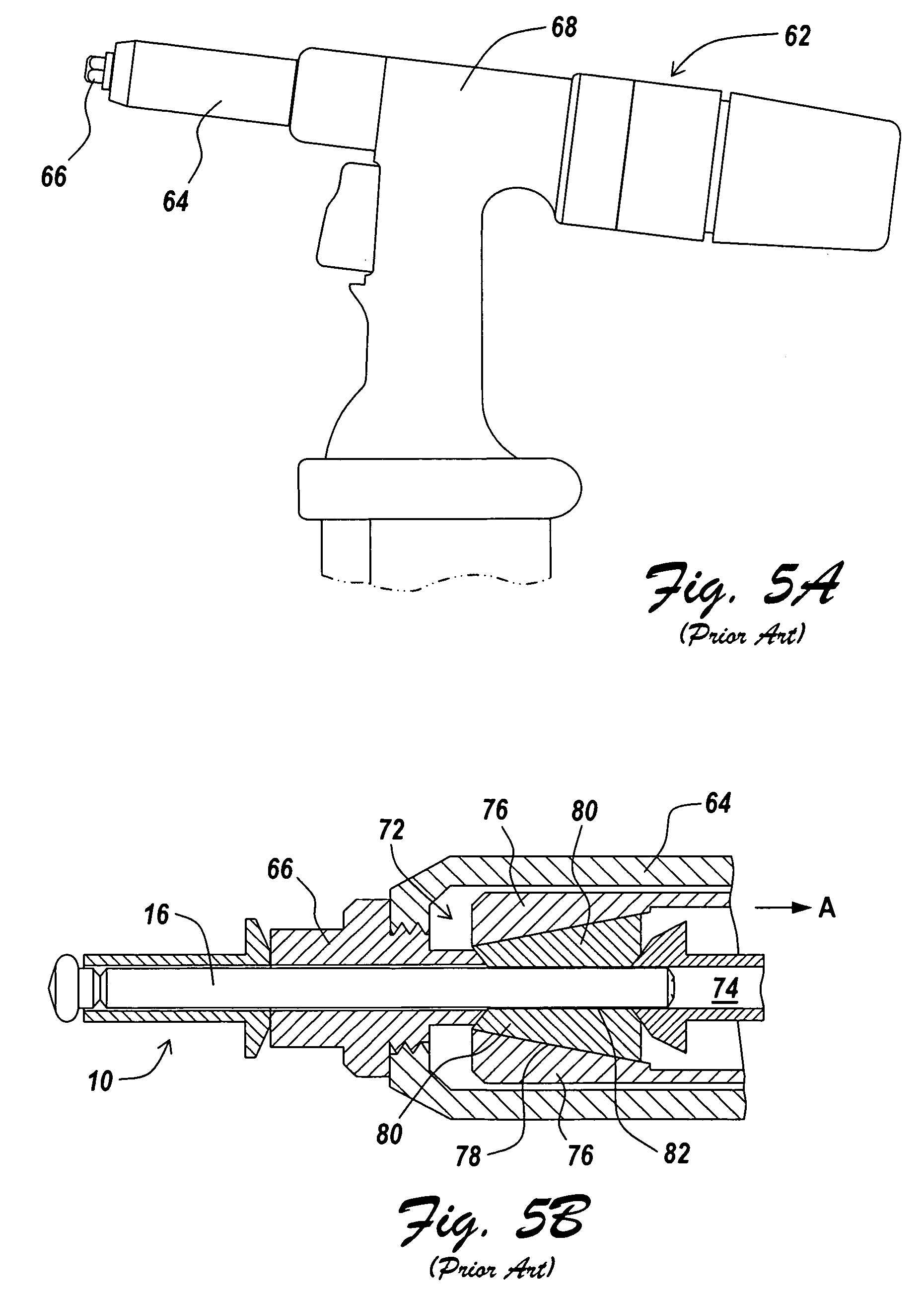
[0034]An illustrative embodiment of the present invention relates to a blind rivet design having an exposed mandrel portion modified from the conventional and standardized mandrel to reduce the amount and cost of the material required to produce the mandrel, while also minimizing costs related to production, use, and spent mandrel disposal, all while still making use of conventional riveting tools for blind rivet setting and maintaining rivet performance. The mandrel is not required to have an unsmooth surface feature for a riveting tool to capture during rivet installation. To work with the inventive blind rivet design, a conventional riveting tool, i.e., a rivet gun with a replaceable nose housing and modified nosepiece, may be utilized, with a modified nose housing attached. The modified nose housing and modified nosepiece on the conventional rivet setting tool enables use of a mandrel having a reduced exposed mandrel portion relative to conventional and standardized mandrels. In...


PUM

PropertyMeasurementUnit
distanceaaaaaaaaaa
distanceaaaaaaaaaa
distanceaaaaaaaaaa

Abstract

A blind rivet design has an exposed mandrel portion modified from the conventional and standardized mandrel to reduce amount and cost of materials required to produce the mandrel, while also minimizing costs related to production, use, and spent mandrel disposal, all while still making use of conventional riveting tools for rivet setting and maintaining rivet performance. To work with the inventive blind rivet design, a conventional riveting tool, i.e., a rivet gun with a replaceable nosepiece, may be utilized, with a modified nose housing attached. The replaceable nosepiece and modified nose housing on the conventional rivet setting tool enables use of a mandrel having a reduced exposed mandrel portion relative to conventional and standardized mandrels. In addition, a modified stepped approach to setting the rivet may also be utilized in conjunction with the inventive rivet design to enable use of an even further reduced exposed mandrel portion.

Description

FIELD OF THE INVENTION[0001]The present invention relates to blind rivets, such as those suitable for joining multiple components of a workpiece together. The present invention is more particularly related to a blind rivet, and corresponding method of use and tool for blind rivet installation, wherein the material required to manufacture the blind rivet is significantly reduced without any detrimental effect to blind rivet fastening performance, thus reducing material quantity and costs.BACKGROUND OF THE INVENTION[0002]Blind rivets are fasteners that are permanently installed in a workpiece 26 (see FIG. 2). Most often, the workpiece 26 is formed of two components or layers, but can be in the form of one to multiple components. When there are multiple components to the workpiece 26, the components are joined together by the blind rivet fastener. Blind rivets are installed from only one side of a workpiece 26, thus being blind to an opposite side. The portion of the rivet on the blind...

Claims


Application Information

Patent Timeline
Patent Type & Authority Applications(United States)
IPC IPC(8): F16B13/08B21D39/03B21J15/02
CPCB21J15/043B21J15/105B21J15/285F16B19/1054B21J15/10F16B13/06Y10T29/49826F16B19/1045F16B19/1063Y10T29/53496Y10T29/5373Y10T29/5377Y10T29/49956F16B19/1036
Inventor TAYLOR, HARRY E.
Owner TAYLOR HARRY E
Why Eureka
Try Eureka