Al technical title is built by PatSnap Al team. It summarizes the technical point description of the patent document.
a magnetic ink and security image technology, applied in the field of security devices, can solve the problems of greater optical illusivity and more difficult counterfeiting
Active Publication Date: 2008-07-17
VIAVI SOLUTIONS INC
View PDF99 Cites 49 Cited by
Summary
Abstract
Description
Claims
Application Information
AI Technical Summary
This helps you quickly interpret patents by identifying the three key elements:
Problems solved by technology
Method used
Benefits of technology
[0019]In accordance with an aspect of the invention, there is provided, a security device comprising a substrate supporting a latent image; and a coating of particles in a carrier supported by the substrate and covering the latent image and aligned in such a manner as to obscure the latent image when viewing the security device from a first angle, and to reveal the latent image when viewing the security device from a second different angle.
Problems solved by technology
Although these prior art references provide some useful and interesting optical effects, there is a need for patterns which have a greater degree of optical illusivity, and which are more difficult to counterfeit.
Method used
Image
Click on the blue label to locate the original text in one second.
Reading with bidirectional positioning of images and text.
Examples
Embodiment Construction
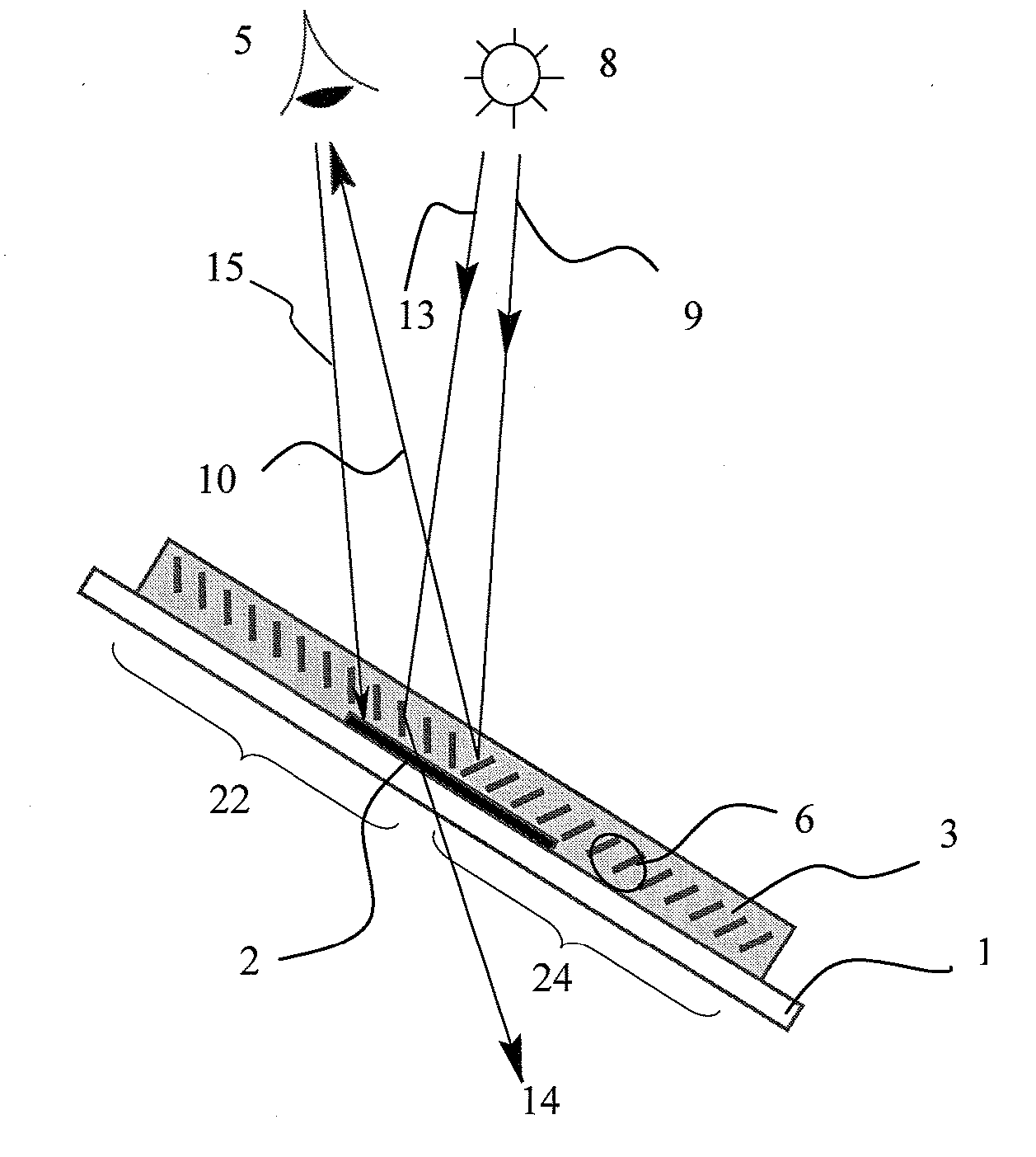
[0040]Within this specification the term “magnetically aligned particles aligned in parallel to one another is meant to be mean particles or flakes that have their faces “substantially parallel” or “as parallel as possible”.
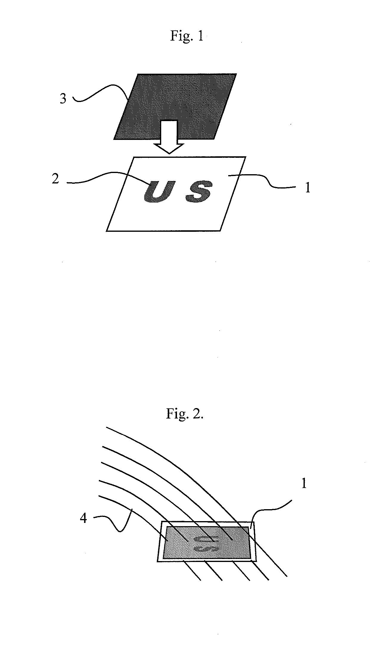
[0041]For example, as can be seen in FIG. 2 field lines propagating through the substrate are “nearly” parallel. Therefore the term parallel, used hereafter is to include “nearly” parallel, or being parallel so as to allow text under the “nearly parallel” flakes to be seen clearly at a particular viewing angle without being substantially obscured.
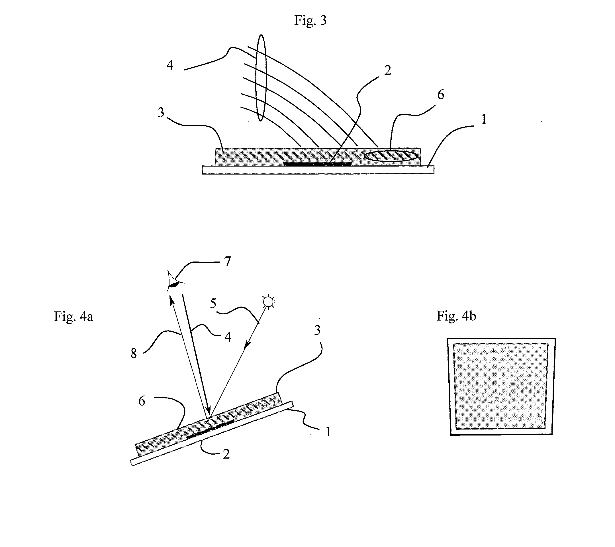
[0042]The term latent image is to mean an image that is present but can only be clearly seen at certain angles of viewing and which is substantially obscured at other viewing angles.
[0043]This invention relates to printing with a semi-transparent ink containing magnetic platelets on the top of a substrate with a previously printed graphic image or text and alignment of the particles at an angle to the plane of the first ...
PUM
Property
Measurement
Unit
reflectance
aaaaa
aaaaa
reflectance
aaaaa
aaaaa
size
aaaaa
aaaaa
Abstract
A security image and method of forming said image is disclosed wherein a substrate having an image or indicia thereon is coated with a dilute solution of pigment flakes in an ink or paint. The flakes are subsequently aligned in a magnetic field and are fixed after the field is applied. Most or all of the flakes in a region are aligned so as to be partially upstanding wherein their faces are essentially parallel. Coating the image with flakes yields a latent image which can be clearly seen at a small range of predetermined angles.
Description
CROSS-REFERENCE TO RELATED APPLICATIONS[0001]This application is a continuation-in-part of U.S. patent application Ser. No. 11 / 415,027 filed May 1, 2006, which claims priority from U.S. Patent application No. 60 / 700,994 filed Jul. 20, 2005, and is a continuation-in-part of U.S. patent application Ser. No. 11 / 028,819 filed Jan. 4, 2005, which is a divisional of U.S. patent application Ser. No. 10 / 243,111 filed Sep. 13, 2002, now U.S. Pat. No. 6,902,807 issued Jun. 7, 2005, which are incorporated herein by reference for all purposes. Also, this application is a continuation-in-part of U.S. patent application Ser. No. 11 / 687,395 filed Mar. 16, 2007, which claims priority from U.S. Patent application No. 60 / 743,609 filed Mar. 21, 2006, which are incorporated herein by reference for all purposes.FIELD OF THE INVENTION[0002]This invention relates generally to a security device and method of forming a security device by coating the surface of a substrate having an image thereon with an ink...
Claims
Application Information
Patent Timeline
Application Date:The date an application was filed.
Publication Date:The date a patent or application was officially published.
First Publication Date:The earliest publication date of a patent with the same application number.
Issue Date:Publication date of the patent grant document.
PCT Entry Date:The Entry date of PCT National Phase.
Estimated Expiry Date:The statutory expiry date of a patent right according to the Patent Law, and it is the longest term of protection that the patent right can achieve without the termination of the patent right due to other reasons(Term extension factor has been taken into account ).
Invalid Date:Actual expiry date is based on effective date or publication date of legal transaction data of invalid patent.
Patent Type & Authority Applications(United States)