Gas treatment systems

a gas treatment system and gas phase technology, applied in dental surgery, combustion types, lighting and heating equipment, etc., can solve the problems of recirculation patterns near the injector, interference with efficient operation or uniform deposition, and unwanted deposition of reaction products on the injector

Active Publication Date: 2008-07-24
VEECO INSTR
View PDF28 Cites 284 Cited by
  • Summary
  • Abstract
  • Description
  • Claims
  • Application Information

AI Technical Summary

Benefits of technology

[0011]One aspect of the invention provides an injector head for a gas treatment reactor. The head according to this aspect of the invention desirably includes a structure defining a plurality of gas inlets having openings facing in a downstream direction. The head further desirably includes diffuser elements disposed between adjacent ones of the gas inlets, the diffuser elements extending in the downstream direction from the gas inlets and tapering in the downstream direction. As further discussed below, the diffuser elements can suppress recirculation of the gases in the vicinity of the injector head.

Problems solved by technology

However, many existing gas injector systems have problems that may interfere with efficient operation or uniform deposition.
For example, precursor injection patterns in existing gas distribution injector systems may contain significant “dead space” (space without active flow from gas inlets on the injector surface) resulting in recirculation patterns near the injector.
These recirculation patterns may result in prereaction of the precursor chemicals, causing unwanted deposition of reaction products on the injector.
Additionally, unwanted deposition may occur on the wall of the reaction chamber.
Such unwanted deposition consumes reactants and decreases the efficiency and reproducibility of the process.
Moreover, reaction products deposited on the injector or on the reactor wall can be dislodged and can contaminate the substrates being processed.
Thus, many current systems require frequent cleaning of the reactor, which further reduces productivity.

Method used


Image

  • Gas treatment systems
  • Gas treatment systems
  • Gas treatment systems

Examples


Embodiment Construction

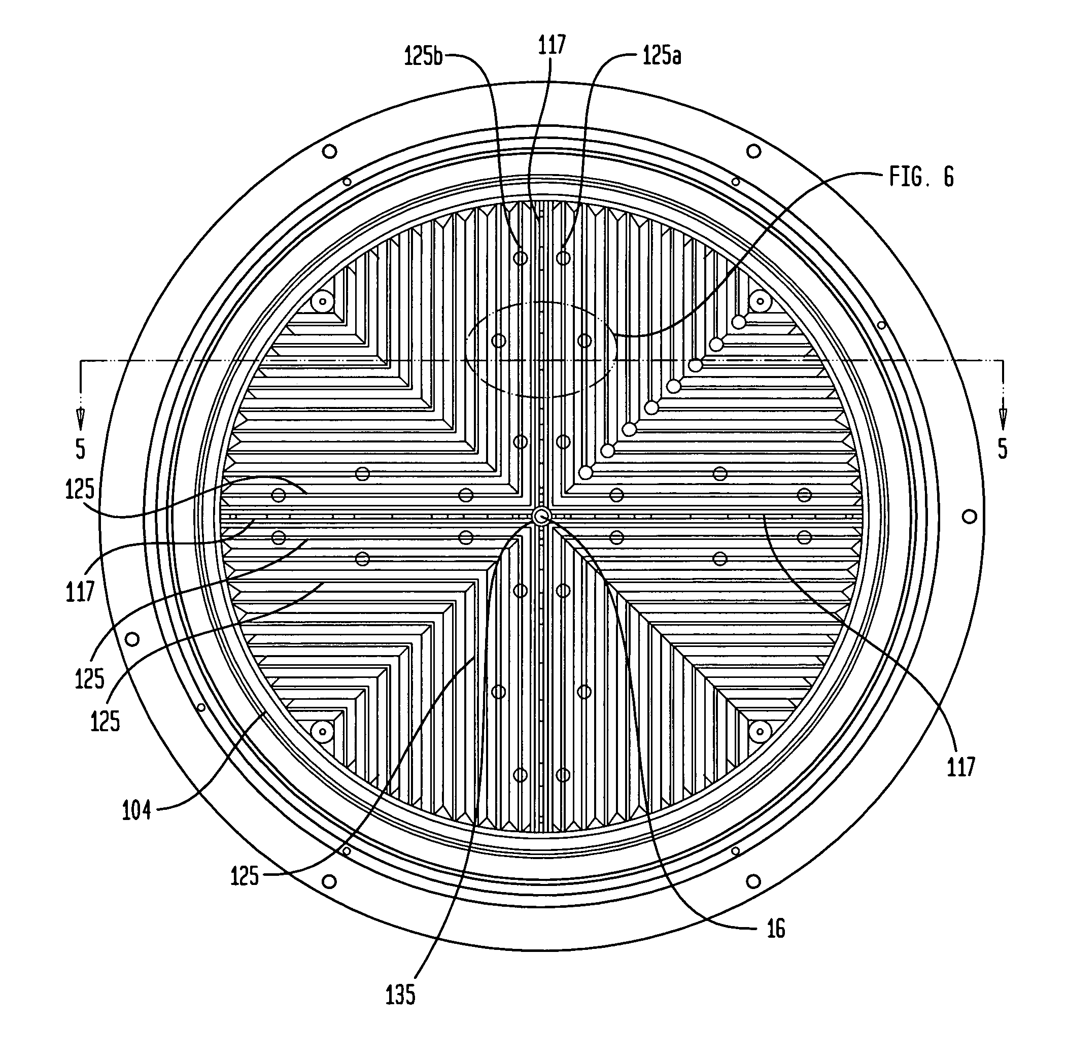
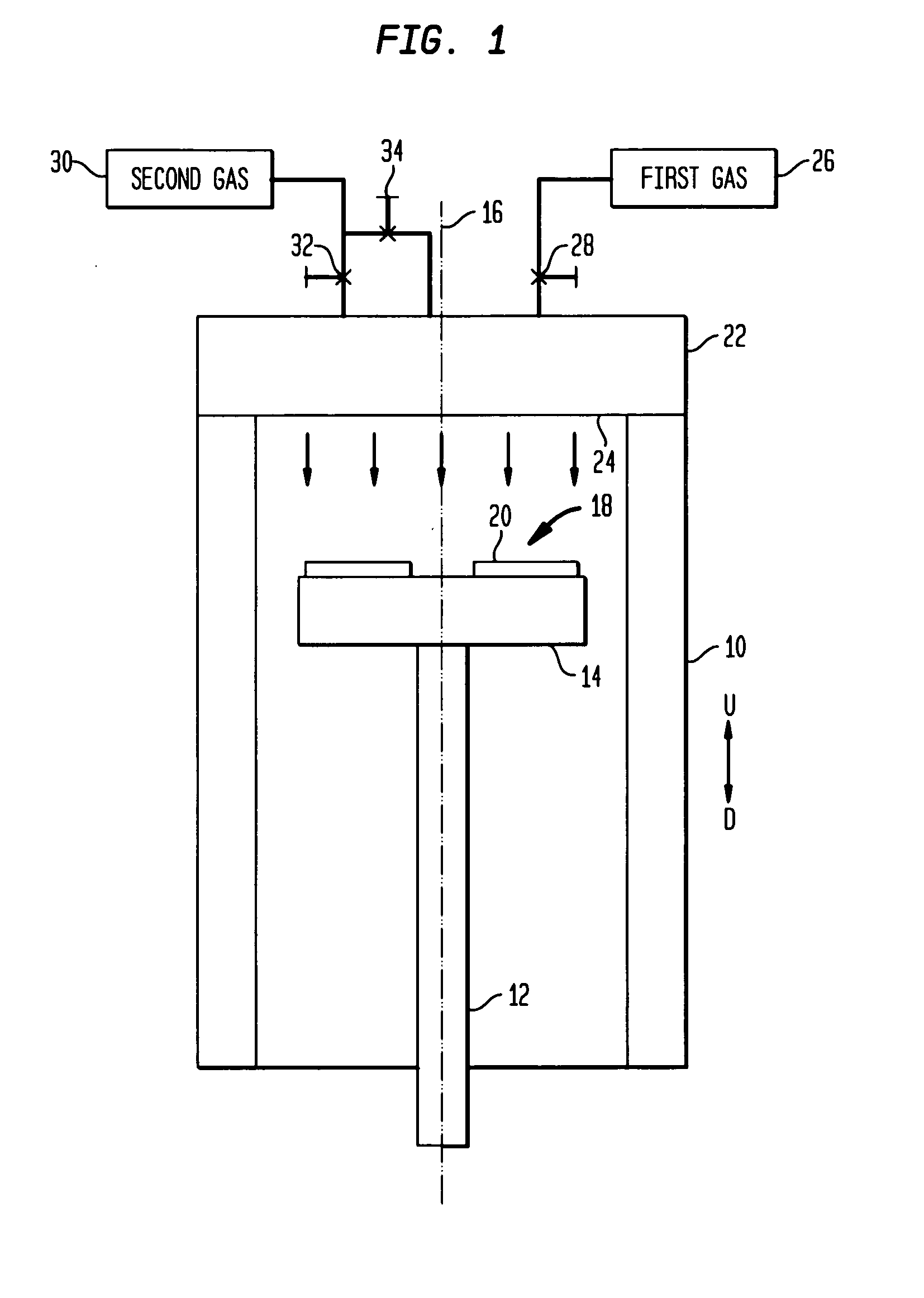
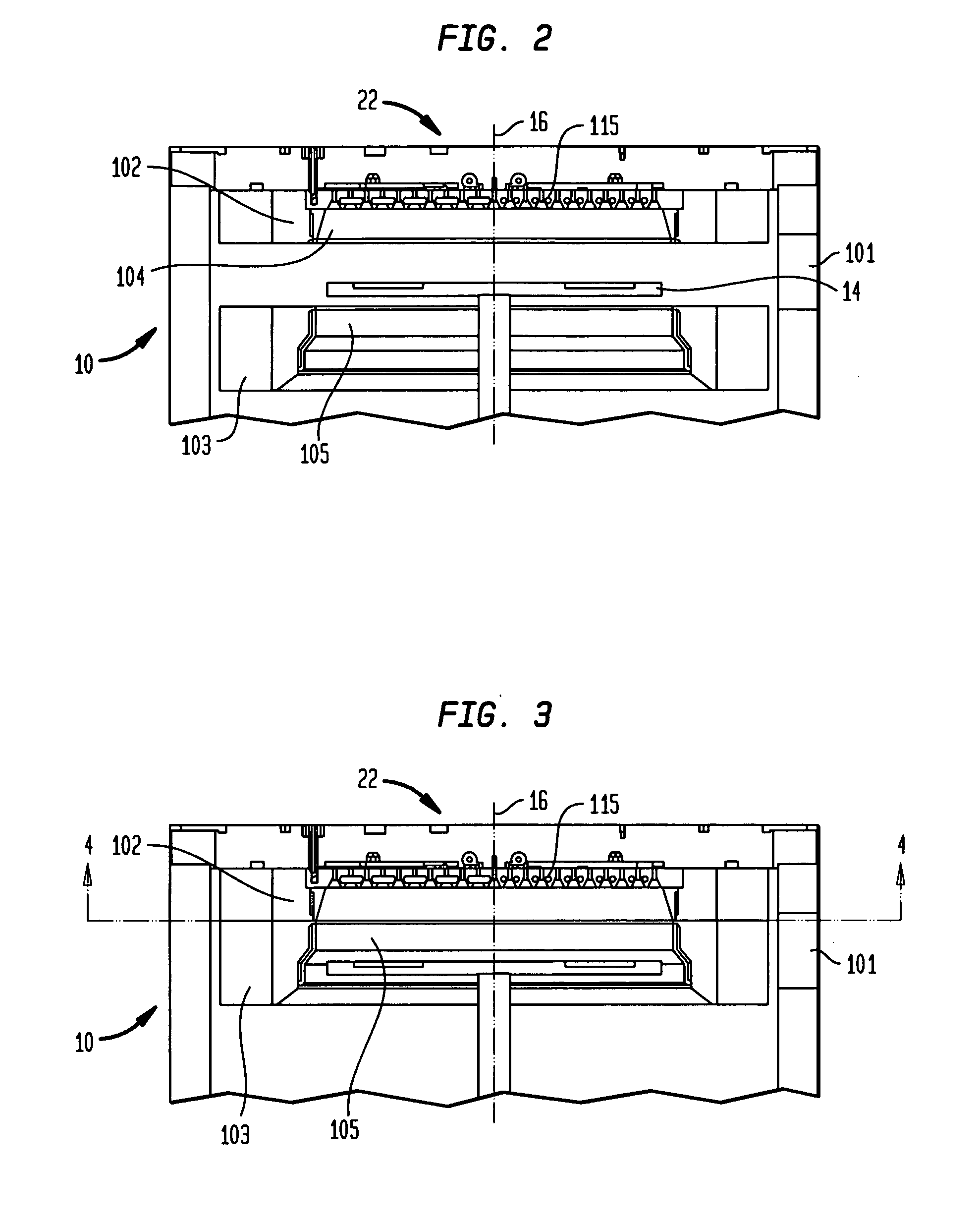
[0024]Referring now to the drawings wherein like numerals indicate like elements, FIG. 1 shows a rotating disk reactor incorporating a multi-gas injector according to one embodiment of the present invention.

[0025]As diagrammatically shown in FIG. 1, the apparatus includes a generally cylindrical reaction chamber 10 which typically has walls formed from stainless steel or other material which is substantially non-reactive with the process gases. The reactor typically includes other components such as a base plate and exhaust ports (not shown). A spindle 12 and a generally disc-like wafer (substrate) carrier 14 are mounted for rotation about an axis 16 coaxial with the cylindrical chamber. Substrates such as wafers 18 are held on the wafer carrier with surfaces 20 of the substrates which are to be treated lying substantially perpendicular to the axis 16 and facing in an upstream direction along the axis indicated by arrow U.

[0026]The substrate carrier and substrates are maintained at ...


PUM

PropertyMeasurementUnit
included angleaaaaaaaaaa
radiusaaaaaaaaaa

Abstract

An MOCVD reactor such as a rotating disc reactor (10) is equipped with a gas injector head having diffusers (129) disposed between adjacent gas inlets. The diffusers taper in the downstream direction. The injector head desirably has inlets (117) for a first gas such as a metal alkyl disposed in radial rows which terminate radially inward from the reactor wall to minimize deposition of the reactants on the reactor wall. The injector head desirably also has inlets (125) for a second gas such as ammonia arranged in a field between the rows of first gas inlets, and additionally has a center inlet (135) for the second gas coaxial with the axis of rotation.

Description

CROSS-REFERENCE TO RELATED APPLICATIONS[0001]The present application claims the benefit of the filing date of U.S. Provisional Patent Application No. 60 / 880,243, filed Jan. 12, 2007, the disclosure of which is incorporated herein by reference.BACKGROUND OF THE INVENTION[0002]This invention relates to systems for reactive gas phase processing such as chemical vapor deposition.[0003]Chemical vapor deposition (“CVD”) reactors permit the treatment of substrates such as wafers mounted on a wafer carrier inside a reaction chamber. A component referred to as a gas distribution injector or injector head is mounted facing towards the wafer carrier. The injector typically includes a plurality of gas inlets that provide some combination of gases to the chamber for chemical vapor deposition. Some gas distribution injectors provide a shroud or carrier gases that assist in providing a laminar gas flow during the chemical vapor deposition process, where the carrier gas typically does not participa...

Claims


Application Information

Patent Timeline
Patent Type & Authority Applications(United States)
IPC IPC(8): F23D11/38
CPCC23C16/45574C23C16/45565C23C16/455H01L21/205
Inventor MITROVIC, BOJANGURARY, ALEXARMOUR, ERIC A.
Owner VEECO INSTR
Why Eureka
Try Eureka