Laser distance finder

a technology of laser and distance finder, which is applied in the field of laser distance finder, can solve the problems of direct influence of the accuracy of the measurement result, large consumption of power by the device, and large reflective member, and achieve the effect of saving power

Inactive Publication Date: 2008-07-24
CHERVON LIMITED
View PDF99 Cites 5 Cited by
  • Summary
  • Abstract
  • Description
  • Claims
  • Application Information

AI Technical Summary

Benefits of technology

[0009]Engagement of the worm's teeth and the transmission part results in a self-locking feature. Thus, when the reflective member reaches a predetermined position, it can be kept on in that position without supplying power to the motor continuously. In this mann

Problems solved by technology

And during the distance measuring, an accuracy of the measuring result is directly affected by drift errors of electrical signals transferred in circuit which are caused by self-heating of electronics elements of the circuit and environmental temperature influences.
A button directly connected to the reflective member is provided in the conventional laser distance finder for a user to

Method used


Image

  • Laser distance finder
  • Laser distance finder

Examples


Embodiment Construction

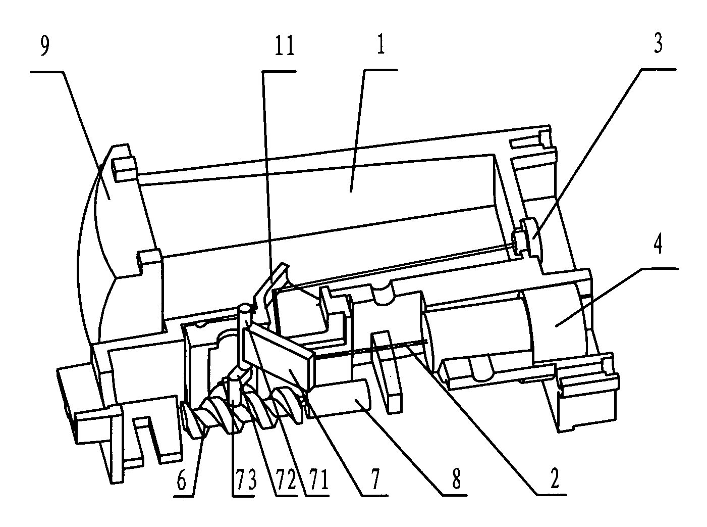
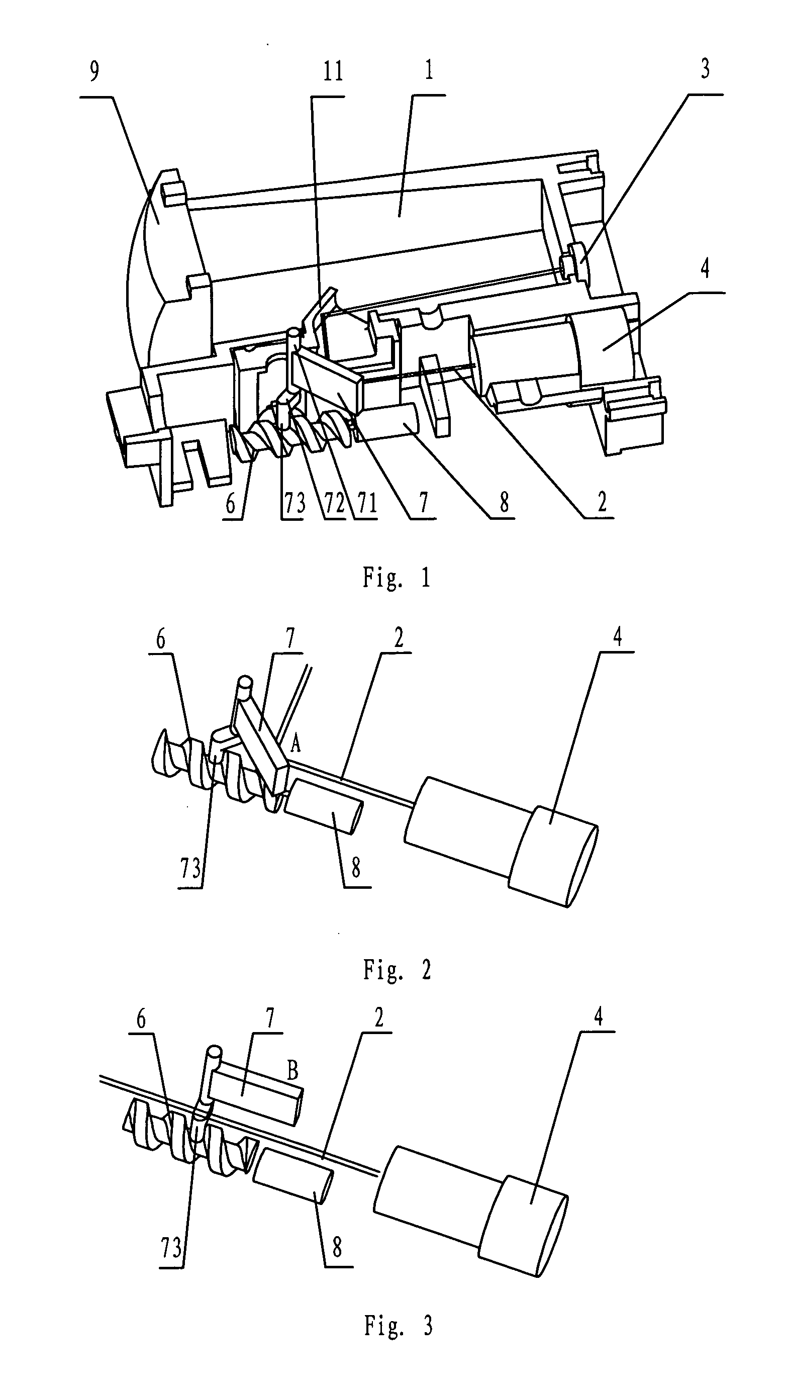
[0014]In a laser distance finder of a preferred embodiment of the present invention shown in FIG. 1, a laser diode (LD) module 4 for emitting a collimating measuring beam 2 is fixedly mounted at one end of a brace 1. A laser generating device is mounted in the LD module 4, and a collimating lens is disposed in an emitting end direction of the laser generating device. The laser generating device and the collimating lens can be mounted on the brace directly. A receiving lens 9 disposed on one side of the LD module 4 is mounted at a front end of the brace 1, and an optoelectronic detector 3 located at a focus point of the receiving lens 9 is mounted at a back end of the brace 1. In the preferred embodiment, the receiving lens 9 is a convex lens, while in other embodiments the receiving lens 9 can be any other suitable lens. The optoelectronic detector 3 may be avalanche photodiode, or PIN photodiode, or other detecting elements or devices. In other embodiments, the laser generating dev...


PUM


Abstract

A compact, power-saving laser distance finder with high accuracy is disclosed having a laser generating device, a collimating lens in an emitting end direction of the laser generating device, a receiving lens, an optoelectronic detector, a reflective member rotatably mounted on an optical path of the collimating measuring beam via a rotating shaft and being capable of rotating to a blocking position and an non-blocking position. There is a transmission part on one end of the reflective member, the transmission part has an interval apart from an axis of the rotating shaft and engages with teeth of a worm driven by motor. When the reflective member reaches a predetermined position, it can be kept at that position through self-locking of the engagement between the worm's teeth and the transmission part without supplying power to the motor continuously, and a distance measuring is carried out and accuracy ensured.

Description

CROSS-REFERENCE TO RELATED APPLICATION[0001]This application claims priority under 35 U.S.C. § 119 of Chinese Application 200720033620.0, filed Jan. 19, 2007, which is hereby incorporated by reference.FIELD OF THE INVENTION[0002]The present invention relates to a distance finder, and more particularly to a laser distance finder for measuring a distance via using light waves.BACKGROUND OF THE INVENTION[0003]Laser distance finders have advantages of being convenient for use, high accuracy, and short measuring time. Laser distance finders are widely used in a variety of applications, such as architecture, exploration, construction and so on.[0004]A known laser distance finder usually comprises a laser generating device, a collimating lens positioned at an emitting end of the laser generating device for converting a laser beam generated from the laser generating device into a collimating measuring beam, a receiving lens disposed on one side of the laser generating device for receiving a...

Claims


Application Information

Patent Timeline
IPC IPC(8): G01C3/00
CPCG01S7/497G01S7/481G01S17/08
Inventor ZHAO, YUZHONG
Owner CHERVON LIMITED
Why Eureka
Try Eureka