

Microphone System with Silicon Microphone Secured to Package Lid
a microphone and silicon technology, applied in the field of microphones, can solve the problems of generally not responding as desired, not appropriately reproducing a received audio signal,
- Summary
- Abstract
- Description
- Claims
- Application Information
AI Technical Summary
Problems solved by technology
Method used
Image

Examples
first embodiment
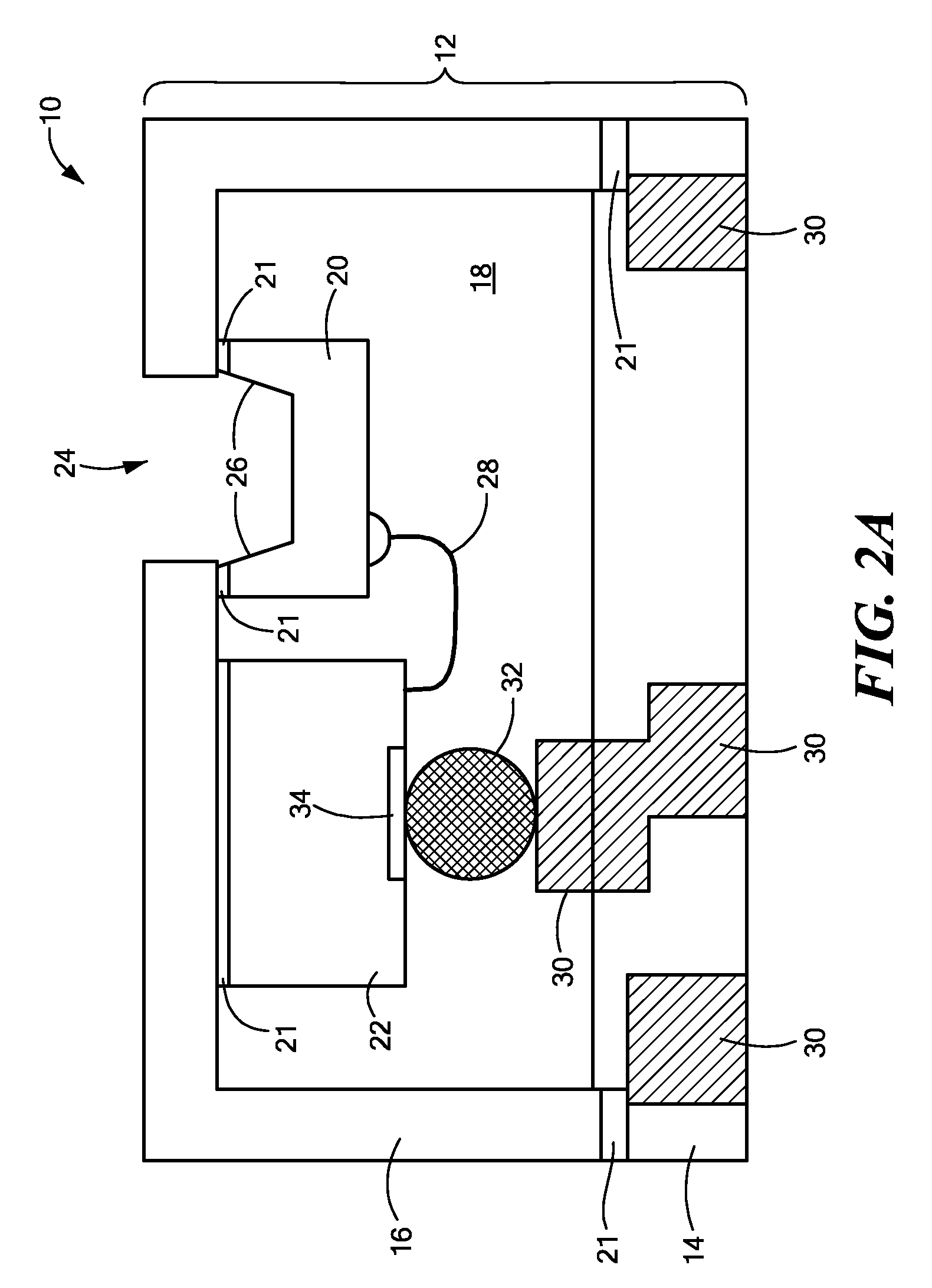
[0033]FIGS. 2A-2D show a variety of different embodiments of the invention. Specifically, FIG. 2A shows a first embodiment in which both the microphone chip 20 and circuit chip 22 directly couple with the lid 16. One or more wirebonds 28 electrically connect the microphone chip 20 to the circuit chip 22. To electrically connect the microphone chip 20 and circuit chip 22 with the substrate, the microphone system 10 also has one or more conductive paths 32 mechanically coupled between the circuit chip 22 and one or more internal contacts 30 on the base 14. Among other things, the conductive path 32 may be a solder ball. As shown, the circuit chip 22 may be considered to mechanically connect with both the lid 16 and the base 14. The microphone chip 20, however, is considered to be mechanically connected with the lid 16 only (i.e., and not mechanically connected with the base 14). A conductive epoxy 21 may electrically ground a portion of the microphone chip 20 to the lid 16. For exampl...
second embodiment
[0034]FIG. 2B schematically shows the invention, in which the microphone chip 20 mechanically connects with both the lid 16 and the base 14. To that end, a conductive or nonconductive epoxy 21 may connect the microphone chip 20 with the lid 16, while one or more solder balls connect the same microphone chip 20 with the base 14. The circuit chip 22, however, mechanically connects with the base 14 only—it does not mechanically connect with the lid 16. As shown, in a manner similar to the microphone chip 20, one or more solder balls 32 electrically and mechanically connect between the circuit chip 22 and the base 14. It should be noted, however, that other techniques, such as those discussed for other embodiments, may be used for electrically and mechanically connecting the circuit chip 22 and microphone chip 20 within the package 12. The base 14 therefore provides the means for electrically communicating between the chips 20 and 22.
[0035]FIGS. 2A and 2B show embodiments in which the m...
third embodiment
[0037]Specifically, FIG. 2C schematically shows a third embodiment in which the microphone chip 20 mechanically couples with the underside of the lid and the top surface of the circuit chip 22. In turn, the circuit chip 22 mechanically and electrically connects with the base 14 by two separate mechanisms. Specifically, the circuit chip 22 mechanically connects with the base 14 by means of an epoxy 21, and electrically connects with the base 14 by means of wire bonds. Accordingly, although the individual chips 20 and 22 do not connect to both the lid 16 and the base 14, they effectively form a stacked up apparatus that connects with both the lid 16 and the base 14.
[0038]FIG. 2D schematically shows another embodiment using a stacked up apparatus, which comprises the two chips 20 and 22. Rather than using separate mechanisms to electrically and mechanically connect with the base 14, this embodiment uses solder bumps / balls 32 both to electrically and mechanically connect the circuit chi...
PUM
 Abstract
Description
Claims
Application Information