
Buckle

Inactive Publication Date: 2008-07-31
YKK CORP
View PDF1 Cites 22 Cited by
  • Summary
  • Abstract
  • Description
  • Claims
  • Application Information

AI Technical Summary

Benefits of technology

[0013]An object of the present invention is to solve the aforesaid problems by providing a buckle that can be easily pinched even when a user pinches front and rear surfaces of a male member to operate the buckle.

Problems solved by technology

However, when the plug has the shape disclosed in JP-A-2005-305112 or JP-A-2002-101915, it is difficult to pinch the front and rear surfaces of the plug.
Especially when the user pinches the central leg strongly, the user may feel pressure on the fingers due to the presence of the rib.
On the other hand, in JP-A-2002-101915, since the front and rear surfaces of the convex portion are substantially flush with the front and rear surfaces of the base of the plug (the base of the leg), the pinching fingers are likely to be displaced from the base, so that it is difficult to pinch the plug at proper positions and the fingers are likely to slip while inserting the plug.

Method used


Image

  • Buckle
  • Buckle
  • Buckle

Examples


embodiment

Description of Embodiment

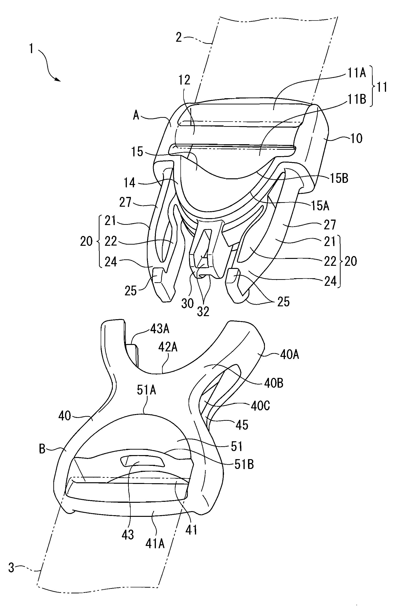
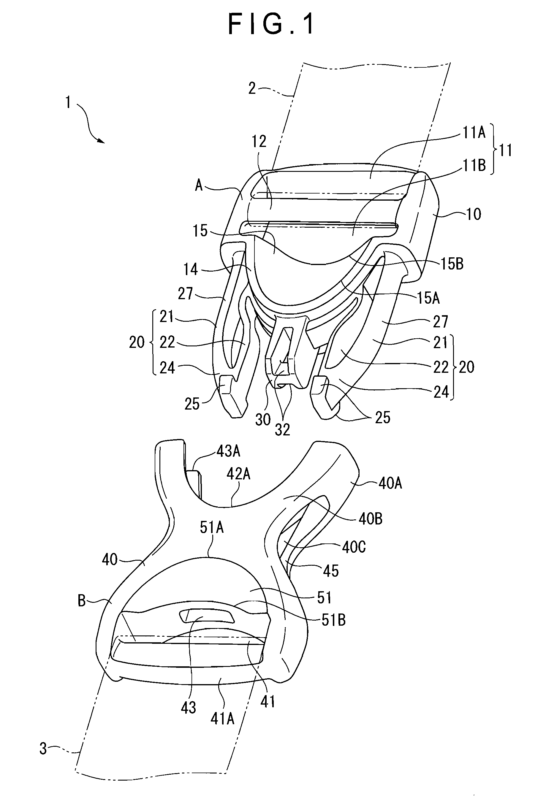
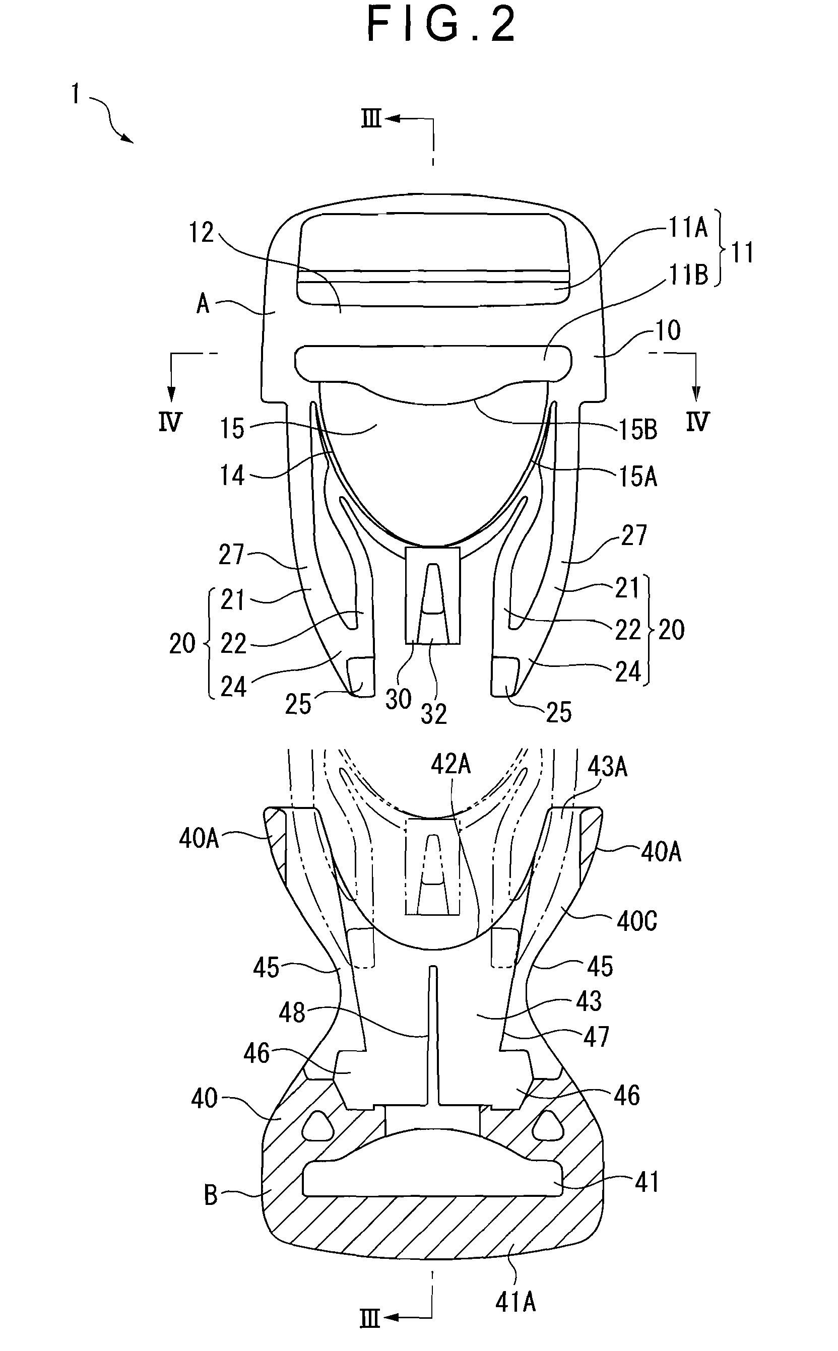
[0051]FIG. 1 is an exploded perspective view of a buckle according to the embodiment. FIG. 2 is a partial cross section showing the buckle in disengagement according to the embodiment. FIG. 3 is a cross section taken along III-III line in FIG. 2. FIG. 4 is a cross section taken along IV-IV line in FIG. 2. FIG. 5 shows a rear end surface of a male member.

[0052]As shown in the figures, a buckle 1 according to the embodiment is used to couple ends 2, 3 of a string member and to separate the coupled ends 2, 3. The buckle 1 includes a male member A integrally formed of synthetic resin; and a female member B also integrally formed of synthetic resin, the male member A being inserted in the female member B to be engaged with the female member B. Note that the male member A and the female member B may not be made of synthetic resin and other materials such as metal can be alternatively used.

[0053]The male member A includes: a base 10; a pair of legs 20 that project ...


PUM


Abstract

A buckle of the present invention includes a male member (A) and a female member (B). The male member includes: a base (10); a pair of legs (20) that project from the base; and engaging portions (25) that are provided on the legs and are engageable with the female member. The base includes a projecting portion (14) that projects in a projecting direction of the legs. A recess (15) is formed on a front or rear surface of the projecting portion. The recess (15) includes a front end (15A) and a rear end (15B) in an inserting direction of the male member (A). The front end substantially has the same height as the front surface of the base. The rear end is substantially lower than any other position on a surface connecting the front end and the rear end.

Description

BACKGROUND OF THE INVENTION[0001]1. Field of the Invention[0002]The present invention relates to a buckle that includes a male member and a female member. Specifically, the invention relates to a buckle that is used to couple and separate ends of a string member or each end of two string members.[0003]2. Description of Related Art[0004]Buckles are used to couple and separate ends of a string member or two string members.[0005]Existing buckles generally include a plug and a socket, a plug-inserting opening of the socket and a base of the plug being linearly formed such that confronting surfaces of the socket and the plug are made linear. However, to provide plug guiding function or to reduce rattling of the inserted plug, a buckle in which a convex portion is provided on a confronting surface of a socket and a concave portion to fit with the convex portion is provided on a confronting surface of a plug has been suggested.[0006]For instance, JP-A-2005-305112 discloses a buckle in whic...

Claims


Application Information

Patent Timeline
IPC IPC(8): A44B11/24
CPCA44B11/266Y10T24/45534Y10T24/45529Y10T24/45581A44B11/00A44B11/25A44B11/26
Inventor YOSHIE, KENICHIOHGAKU, MIYUKI
Owner YKK CORP
Learn More