Preform Spar Cap for a Wind Turbine Rotor Blade

a technology of composite components and spar caps, which is applied in the manufacture of final products, machines/engines, wind energy generation, etc., can solve the problems of spar caps made from composite materials of fibrous materials that wrinkle or bunch around the inside curve, and the efficiency of wind turbines, so as to promote easy and low-cost transportation, maintain the strength and structural integrity of fiber materials

Active Publication Date: 2008-07-31
GENERAL ELECTRIC CO
View PDF14 Cites 78 Cited by
  • Summary
  • Abstract
  • Description
  • Claims
  • Application Information

AI Technical Summary

Problems solved by technology

However, as the physical sizes and availability of wind turbines increase, so does the need to balance the cost of manufacturing and operating wind turbines to further allow wind power to be cost-competitive with other energy sources.
However, size and shape produce opposite effects on efficiency an increase in rotor blade size increases the energy production of a wind turbine, while a decrease in weight also furthers the efficiency of a wind turbine.
However, a problem with the current state of the art is that the spar caps made from composites of fibrous materials wrinkle or bunch around the inside curve when formed into a swept shape.
For larger rotor blades, regardless of their shape, problems exist in creating the spar caps that are strong enough without adding excessive weight to the rotor blades.
Further, the larger the rotor blade the larger the spar cap is, and therefore, the transportation of the spar caps from the place of manufacture to the assembly location becomes increasingly difficult with size.

Method used


Image

  • Preform Spar Cap for a Wind Turbine Rotor Blade
  • Preform Spar Cap for a Wind Turbine Rotor Blade
  • Preform Spar Cap for a Wind Turbine Rotor Blade

Examples


Embodiment Construction

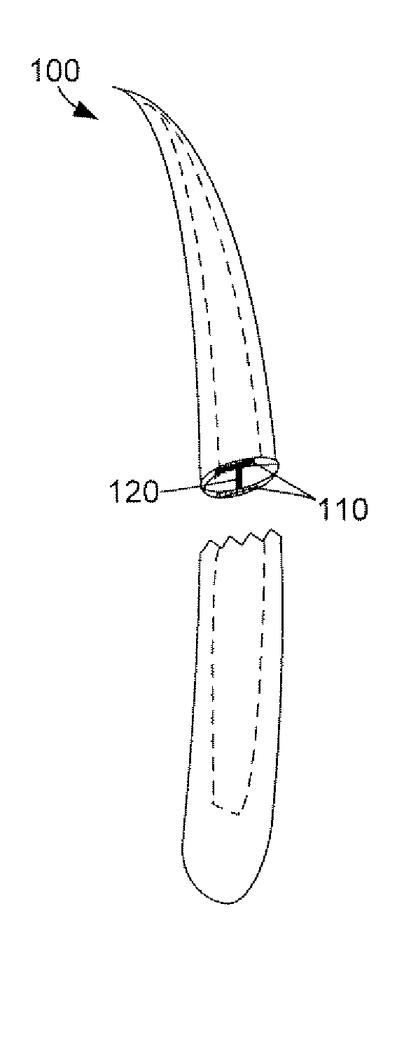
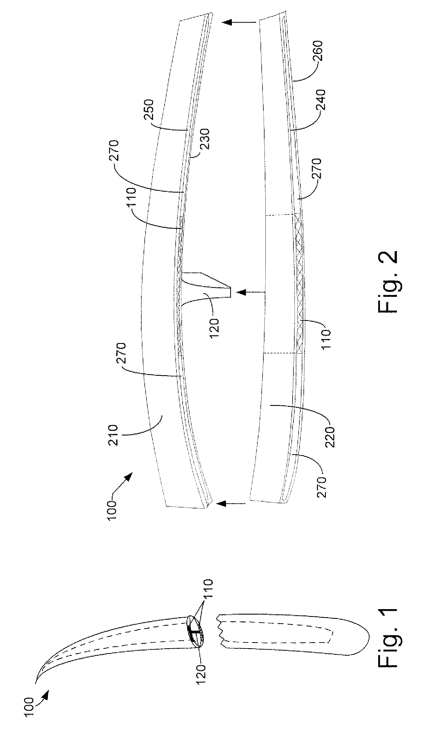
[0022]Referring now to the drawings, in which like numerals indicate like elements throughout the several views, FIG. 1 is an exemplary illustration of a rotor blade 100 with a cross section removed showing a pair of spar caps 110 and a shear web 120 integrated therein. The rotor blade 100 may be used, for example, in a wind turbine. The rotor blade 100 may have a swept shape giving it a curved contour running from the distal end to the proximal end of the rotor blade 100. At least two spar caps 110 may be integrated within the rotor blade 100, generally running from its distal end to its proximal end and having generally the same swept shape as the rotor blade 100. At least one shear web 120 may also run generally from the distal to the proximal end of the rotor blade 100, may have generally the same swept shape, and may be joined to the inside surfaces of each spar cap 110 at an approximately perpendicular orientation. It should be appreciated that the same general configuration, ...


PUM

PropertyMeasurementUnit
poweraaaaaaaaaa
angleaaaaaaaaaa
shapeaaaaaaaaaa

Abstract

A spar cap for a wind turbine rotor blade. The spar cap may include multiple preform components. The multiple preform components may be planar sheets having a swept shape with a first end and a second end. The multiple preform components may be joined by mating the first end of a first preform component to the second end of a next preform component, forming the spar cap.

Description

STATEMENT REGARDING FEDERALLY SPONSORED RESEARCH OR DEVELOPMENT[0001]The federal government may have certain rights in this invention by virtue of the United States Department of Energy Contract No. DE-AC36-99-GO10337 and Contract No. ZAM43123505.TECHNICAL FIELD[0002]The present application relates generally to preform composite components and more particularly relates to spar caps having preform composite components and methods of manufacturing spar caps having perform composite components.BACKGROUND OF THE INVENTION[0003]Wind power and the use of wind turbines have gained increased attention as the quest for alternative energy sources continues. Wind power may be considered one of the cleanest, most environmentally friendly energy sources presently available. Different from traditional fossil fuel sources, wind power is completely renewable and does not produce noxious or environmentally harmful bi-products. With an increasing attention towards generating more energy from wind pow...

Claims


Application Information

Patent Timeline
Patent Type & Authority Applications(United States)
IPC IPC(8): B64C11/20
CPCF03D1/0675Y10T29/49826Y10T29/49336Y02E10/721Y02E10/72Y02P70/50
Inventor LIVINGSTON, JAMIE T.DRIVER, HOWARD D.VAN BREUGEL, SJEFJENKINS, THOMAS B.BAKHUIS, JAN WILLEMBILLEN, ANDREW J.RIAHI, AMIR
Owner GENERAL ELECTRIC CO
Why Eureka
Try Eureka