Magnetic head

a magnetoresistive head and head technology, applied in the field of magnet head, can solve the problems of mainly dependent resistance of electric noise, and achieve the effect of reducing mag-noise, improving snr of magnetoresistive head, and without deterioration in reproduced outpu

Active Publication Date: 2008-07-31
WESTERN DIGITAL TECH INC
View PDF6 Cites 14 Cited by
  • Summary
  • Abstract
  • Description
  • Claims
  • Application Information

AI Technical Summary

Benefits of technology

[0004]Embodiments of the present invention help to reduce mag-noise in a magnetoresistive head without deterioration in reproduced output and improve the SNR of the magnetoresistive head. According to the particular embodiment of FIG. 1, the magnetoresistive head uses a synthetic ferri free layer and is arranged such that the magnetic field which is applied to an end of a free layer 1 with smaller film thickness and saturation magnetization in the track width direction by a coupling field, is larger than the magnetic field which is applied to it by a bias layer 21.

Problems solved by technology

On the other hand, electric noise mainly depends on resistance.

Method used


Image

  • Magnetic head
  • Magnetic head
  • Magnetic head

Examples


embodiment 1

[0079]A second structural example of embodiments of the present invention will be described next. In this structural example, the film thickness of the free layer anti-parallel coupling layer 11 is 0.35 nm or more and 0.45 or less. This corresponds to the first peak for the free layer anti-parallel coupling layer 11's film thickness as shown in FIG. 19. The exchange coupling energy at this point is as large as 1.2 (erg / cm2), which means that favorable magnetic domain control and mag-noise reduction can be achieved with a wider film thickness of the free layer anti-parallel coupling layer 11 than in FIGS. 20 to 23, explained below, show structural examples in which the free layer anti-parallel coupling layer 11's thickness is 0.35 nm or more and 0.45 or less.

[0080]FIG. 19 shows the relation between exchange coupling energy and film thickness t_Ru of the free layer anti-parallel coupling layer 11. From FIG. 19, it is known that when the free layer anti-parallel coupling layer 11's th...

embodiment 3

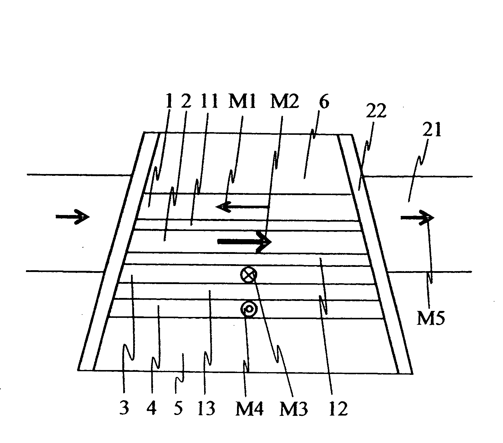
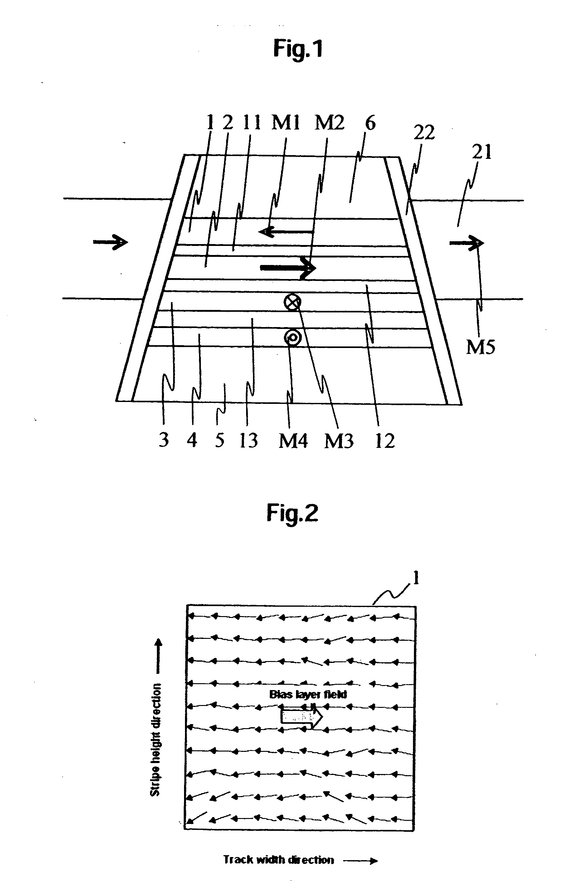
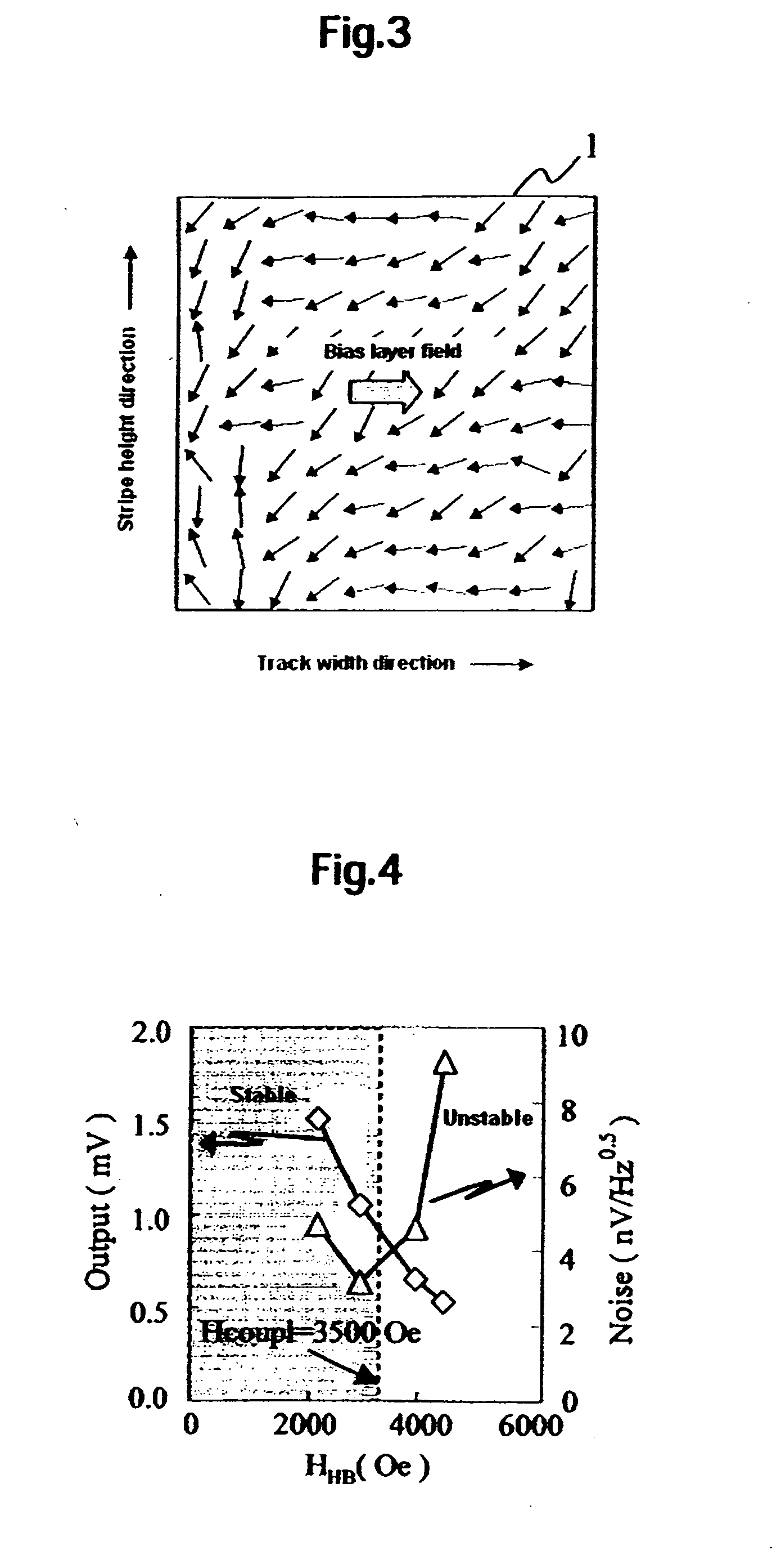
[0092]As discussed earlier, in order to suppress noise which occurs when magnetization M1 of first ferromagnetic layer 1 is tilted by the magnetic field applied from the bias layer 21, the bias field applied to the first ferromagnetic layer 1 must be smaller than the magnetic field applied to the first ferromagnetic layer by anti-ferromagnetic coupling of the first and second ferromagnetic layers. However, if the bias field is below a certain value, magnetic domain control of the second ferromagnetic layer would become impossible and the problem of nonlinear reproduced waveform or the like would arise. However, , suppression of the first ferromagnetic layer's noise characteristic of the synthetic ferri free layer and optimal magnetic domain control of the second ferromagnetic layer can be both achieved more reliably.

[0093]This structural example is an example that the shape magnetic anisotropy field (Hshape) is not negligible for a hard-bias field in embodiment 1. In this structural...


PUM

PropertyMeasurementUnit
thicknessaaaaaaaaaa
thicknessaaaaaaaaaa
thicknessaaaaaaaaaa

Abstract

Embodiments of the present invention help to reduce mag-noise in a magnetoresistive head without deterioration in reproduced output and improve the signal/noise ratio (SNR) of the magnetoresistive head. According to one embodiment, the magnetoresistive head uses a synthetic ferri free layer and it is arranged such that the magnetic field which is applied to an end of a free layer with smaller film thickness and saturation magnetization in the track width direction by a coupling field is larger than the magnetic field which is applied to it by a bias layer.

Description

CROSS-REFERENCE TO RELATED APPLICATION[0001]The instant nonprovisional patent application claims priority to Japanese Patent Application No. 2007-017041 filed Jan. 26, 2007 and which is incorporated by reference in its entirety herein for all purposes.BACKGROUND OF THE INVENTION[0002]A magnetoresistive head is used as a read sensor in high recording density magnetic recording technology focusing on hard disk drives and largely influences magnetic recording technological performance. In recent years, it has been well known that the magnetoresistance effect of a multilayered film in which ferromagnetic metal layers are stacked through a nonmagnetic metal layer, the so-called giant magnetoresistance (GMR) effect, is large. In this case, electric resistance changes depending on relative angle of magnetizations of two ferromagnetic layers with a nonmagnetic interlayer. For the use of this giant magnetoresistance effect in magnetoresistive sensors, a structure called a “spin valve” has be...

Claims


Application Information

Patent Timeline
Patent Type & Authority Applications(United States)
IPC IPC(8): G11B5/39
CPCB82Y10/00B82Y25/00Y10T428/1121G11B2005/3996G11B5/3906
Inventor SHIIMOTO, MASATOKATADA, HIROYUKINAKAMOTO, KAZUHIROHOSHIYA, HIROYUKI
Owner WESTERN DIGITAL TECH INC
Why Eureka
Try Eureka