Fluid supply monitoring system

a monitoring system and fluid supply technology, applied in the direction of fluid tightness measurement, water supply installation, instruments, etc., can solve the problems of small or large leakage of fluid supply system, failure of fluid supply components, and significant damage to buildings

Inactive Publication Date: 2008-08-07
BRASSCRAFT MFG CO +1
View PDF27 Cites 44 Cited by
  • Summary
  • Abstract
  • Description
  • Claims
  • Application Information

AI Technical Summary

Benefits of technology

[0007]A method for testing a fluid supply system includes periodically preventing a fluid flow through the fluid suppl...

Problems solved by technology

These fluid supply components are subject to failure.
A failed component may result in small or large leaks within the fluid supply system.
Disadvantageously, the leaks may cause significant damage to the building from flooding, water damage, fire risk and the like.
However, these systems are complicated, and difficult to...

Method used


Image

  • Fluid supply monitoring system
  • Fluid supply monitoring system
  • Fluid supply monitoring system

Examples


Embodiment Construction

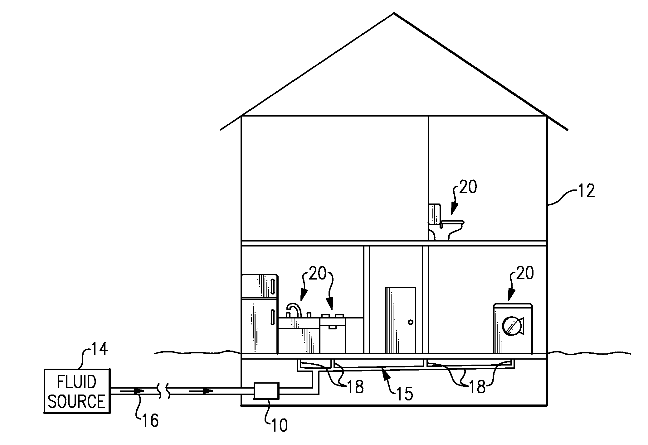
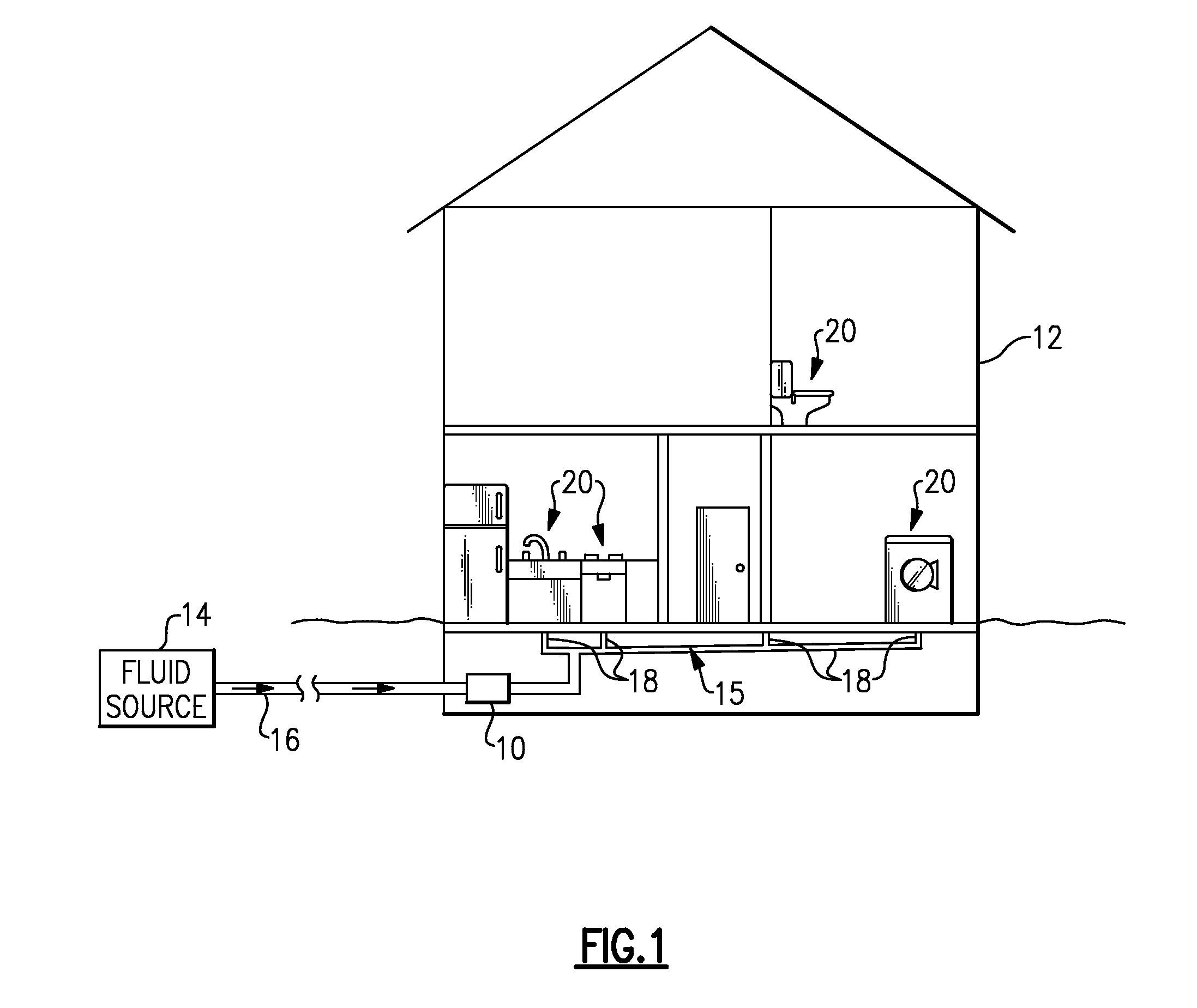
[0024]FIG. 1 illustrates a fluid supply monitoring system 10 that monitors the communication of a fluid through a building 12, such as an industrial, commercial or residential building 12, for example. Fluid from a fluid source 14 is communicated to the building via a fluid supply line 16. In one example, the fluid is water. In another example, the fluid is a gas. It should be understood that the example fluid supply monitoring system 10 may be utilized to monitor the flow of any known fluid.

[0025]Once in the building 12, the fluid supply line 16 communicates the fluid to a fluid supply system 15. In one example, the fluid supply system 15 is a plumbing system. In another example, the fluid supply system 15 is a gas supply system. A person of ordinary skill in the art having the benefit of this disclosure would be able to implement the example fluid supply monitoring system 10 into any type of fluid supply system to monitor the flow of any fluid type.

[0026]The fluid supply system 15...


PUM


Abstract

A method for testing a fluid supply system includes periodically preventing a fluid flow through the fluid supply system, and measuring a system pressure of the fluid flow subsequent to the step of preventing the fluid flow.

Description

CROSS-REFERENCE TO RELATED APPLICATIONS[0001]This application claims priority to U.S. Provisional Application No. 60 / 899,524, filed Feb. 5, 2007.BACKGROUND OF THE INVENTION[0002]This disclosure generally relates to a fluid supply system, and more particularly to a method of testing a fluid supply system.[0003]Fluids, such as water and / or gas, are supplied to most residential, commercial and industrial buildings via underground supply lines. Supply lines receive the fluid from either a municipal source or a private well, for example. The underground supply lines interconnect with a fluid supply system. The fluid supply system communicates the fluid to a variety of outlets and appliances within the building. For example, the fluid supply system may include a plumbing system that communicates water to toilets, sinks, washing machines, dishwashers and the like.[0004]The fluid supply system typically includes a plurality of supply lines that distribute the fluid to a plurality of locatio...

Claims


Application Information

Patent Timeline
IPC IPC(8): G01M3/26E03B1/00
CPCF17D5/06G01M3/28G01M3/022Y10T137/776Y10T137/8158Y10T137/0379Y10T137/2579Y10T137/7723Y10T137/7727Y10T137/8593Y10T137/7062
Inventor MULLIGAN, TIMOTHY DAVIDMILLAR, DAVIDLONDON, AARON ROSSPARRISH, DAVID MICHAELBAKER, LINDON ALFORDGROS, RICHARD ALAN
Owner BRASSCRAFT MFG CO
Why Eureka
Try Eureka