Injection mold and partial compression molding method

a molding method and injection mold technology, applied in the field of injection molds, can solve the problems of unnecessary and complicated driving sources, such as hydraulic cylinders or air cylinders, and achieve the effect of preventing sink marks and superior appearan

Inactive Publication Date: 2008-08-07
CANON KK
View PDF6 Cites 13 Cited by
  • Summary
  • Abstract
  • Description
  • Claims
  • Application Information

AI Technical Summary

Benefits of technology

[0009]The present invention provides an injection mold and an injection molding method that obtain a molded item having superior appearance by preventing a sink mark from being formed on the back of a rib or a boss of the molded item.
[0012]According to the present invention, since a compression boss is not formed at the start of resin filling and resin flows along the cavity, nonuniform flow can be avoided. Further, since a compression boss is automatically formed by the pressure of resin, a complicated driving source, such as a hydraulic cylinder or an air cylinder, is unnecessary. This can simplify the mold structure and can reduce the mold cost. In addition, a sink mark is prevented from being formed on an outer surface of a rib or a boss by partially compressing the compression boss, and nonuniform transfer and uneven glossiness can be prevented from being caused by formation of the compression boss.

Problems solved by technology

Further, since a compression boss is automatically formed by the pressure of resin, a complicated driving source, such as a hydraulic cylinder or an air cylinder, is unnecessary.

Method used


Image

  • Injection mold and partial compression molding method
  • Injection mold and partial compression molding method
  • Injection mold and partial compression molding method

Examples


Embodiment Construction

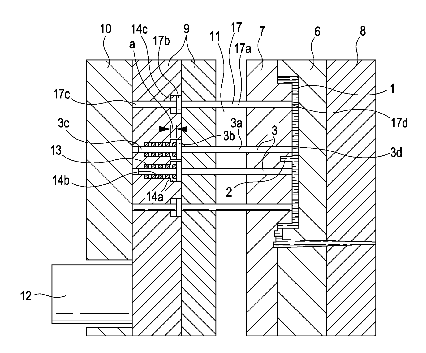
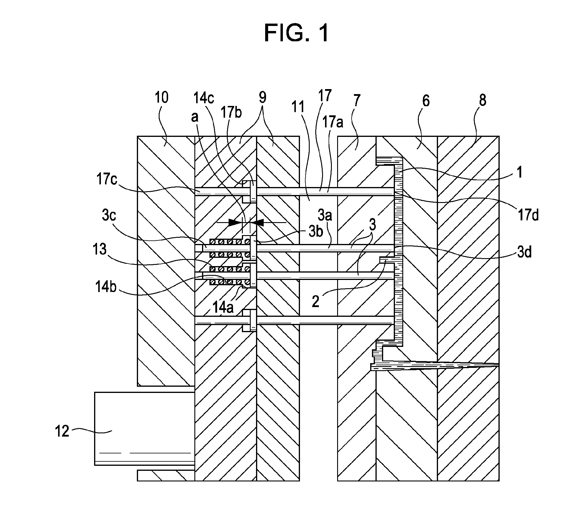
[0023]An exemplary embodiment of the present invention will be described with reference to the drawings. FIG. 1 is a cross-sectional view showing the principal part of an injection mold according to the exemplary embodiment. Referring to FIG. 1, a stationary mold section 6 is fixed to a stationary clamping plate 8. A movable mold section 7 is attached to and held by a movable clamping plate 10 with a spacer block (not shown) disposed therebetween. A cavity 1 is defined between the stationary mold section 6 and the movable mold section 7. Further, a space 11 is formed between the movable mold section 7 and the movable clamping plate 10 by the spacer block. In the space 11, a pair of ejector plates 9 are provided so as to be pushed toward the cavity 1 by an ejector rod 12 that is driven by an ejector cylinder (not shown). Compression pins 3 extend through the ejector plates 9. Each compression pin 3 includes a front end portion 3a, a flange portion 3b, and a rear end portion 3c. A bia...


PUM

PropertyMeasurementUnit
pressureaaaaaaaaaa
diameteraaaaaaaaaa
elasticaaaaaaaaaa

Abstract

In an injection mold, a compression pin is placed at a cavity surface by the pressing force of a biasing member, and is moved rearward by the pressure of filled resin so as to form a compression boss. After the completion of filling, the compression boss is compressed by the compression pin.

Description

BACKGROUND OF THE INVENTION[0001]1. Field of the Invention[0002]The present invention relates to an injection mold used to form a resin molded item, and a partial compression method for the injection mold.[0003]2. Description of the Related Art[0004]In a mold for partial compression molding disclosed in Japanese Patent Laid-Open No. 5-228970, depressions are formed by moving ejector pins back away from a mold surface, which forms an inner surface of a molded item, by a compression allowance. The depressions and a cavity are filled with resin in this state, and the resin is then compressed by the ejector pins. Japanese Patent Laid-Open No. 11-198198 discloses that the leading end of a boss is compressed by an ejector pin and that a peripheral portion of the boss is compressed by a sleeve pin. Further, Japanese Patent Laid-Open No. 2002-283422 discloses that an inner portion of a boss is compressed.[0005]A known partial compression molding method will be described below with reference...

Claims


Application Information

Patent Timeline
Patent Type & Authority Applications(United States)
IPC IPC(8): B29C45/80
CPCB29C45/0025B29C45/572B29C45/561
Inventor UEZAKI, TERUAKIARAI, TAKASHIIITSUKA, YOSHIHIRO
Owner CANON KK
Why Eureka
Try Eureka