

Laparoscopic hernia mesh spreader
a mesh spreader and hernia technology, applied in the field of laparoscopic deployment and positioning of surgical materials, can solve the problems of arduous mesh movement, and achieve the effect of improving the stability and stability of the mesh
- Summary
- Abstract
- Description
- Claims
- Application Information
AI Technical Summary
Problems solved by technology
Method used
Image

Examples
example 1
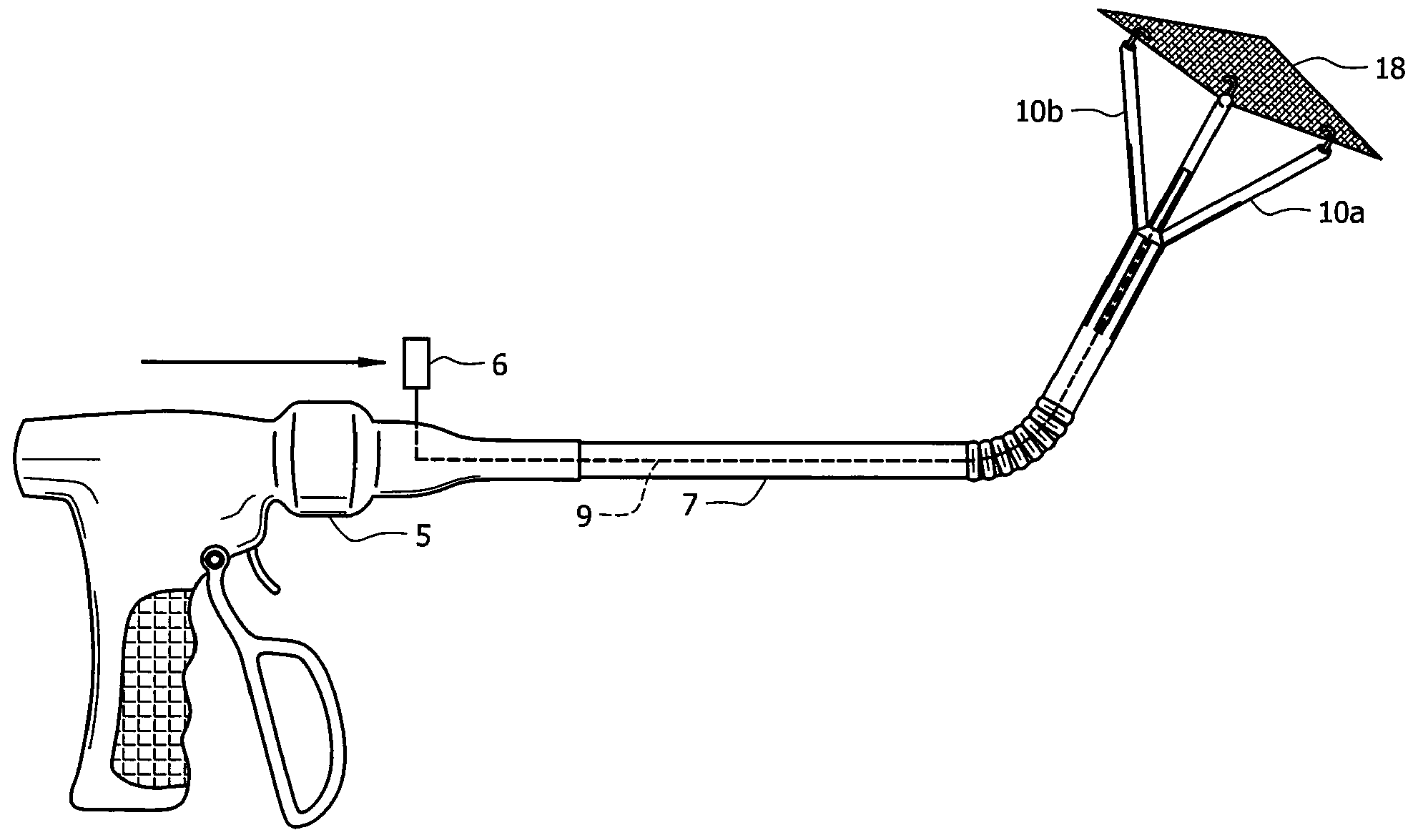
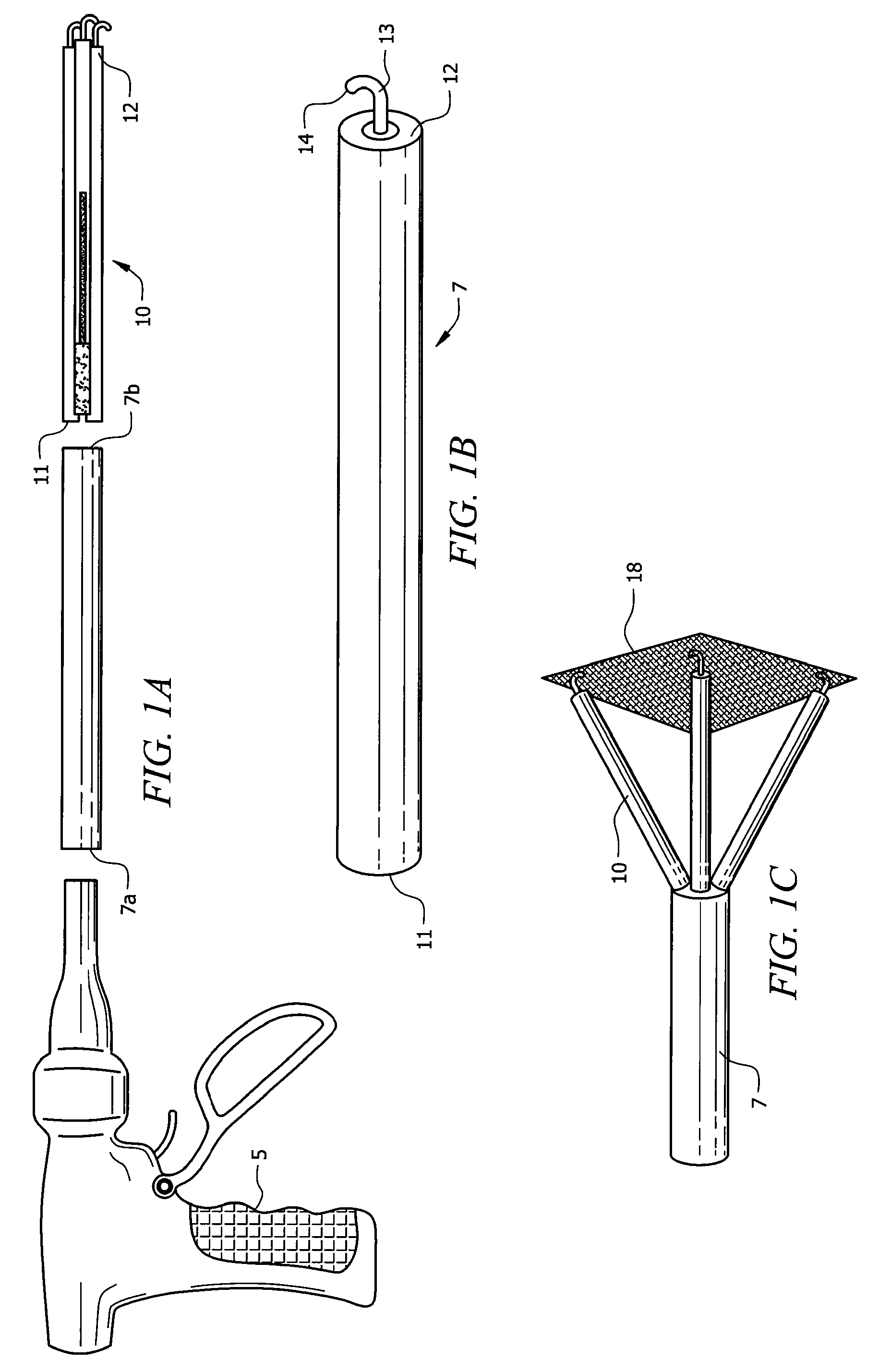
Rigid Arm Mesh Spreader
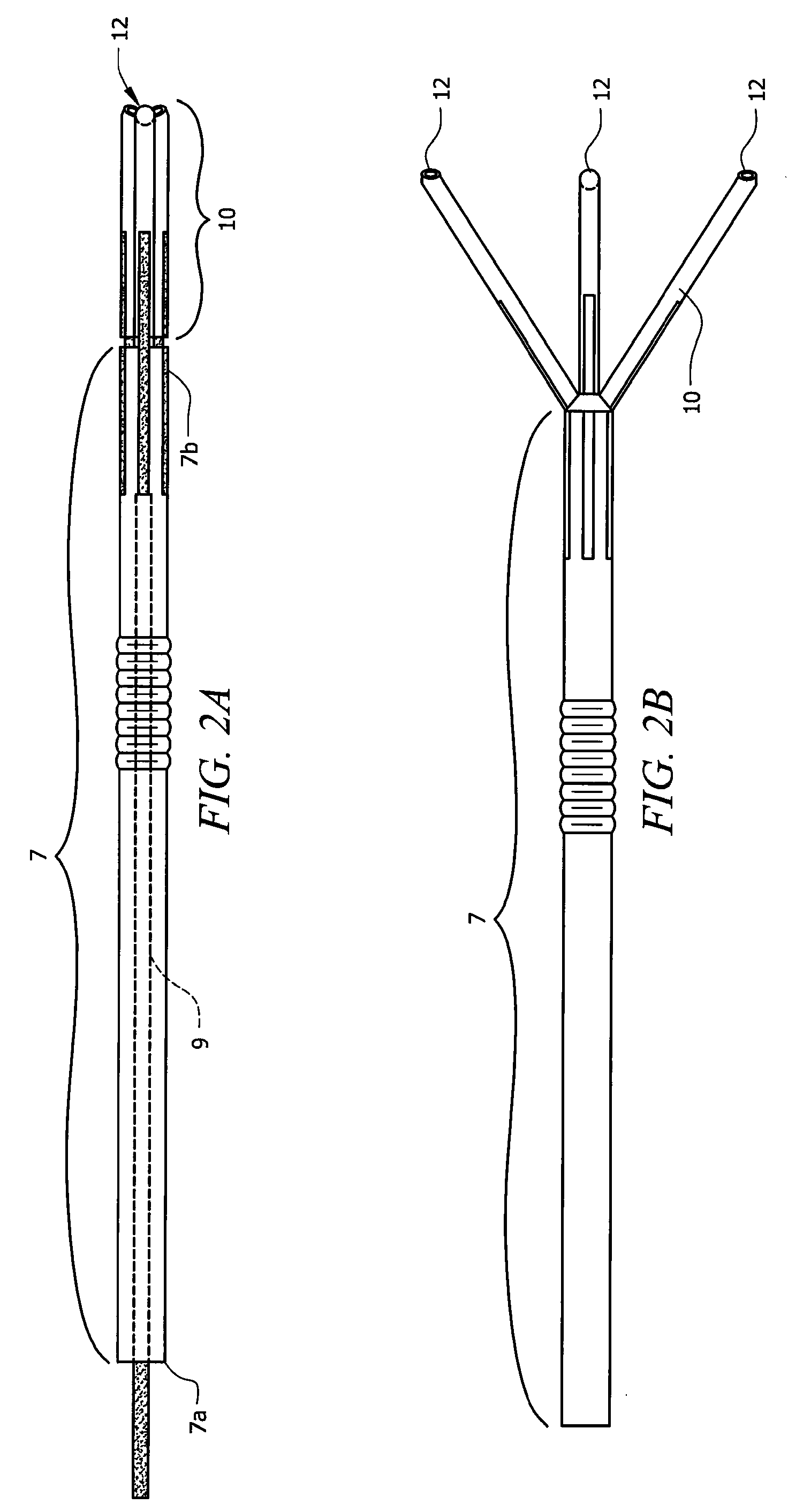
[0033]An embodiment employing a plurality of substantially rigid extension arms is shown in FIGS. 1A through 1C and 2A through 2B. Here, a substantially rigid rod 9 is mounted within shaft 7. Rod 9 is connected to a lever on handle 5 at its proximal end, and extension arms 10 at its distal end. extension arms 10 are hingidly connected to the distal end of rod 9. The action of the hinges is preferably in a single, predetermined plane such as that of an elbow joint. This allows predictable deployment of the mesh when the extension arms are activated.
[0034]One embodiment uses hollow cylindrical hinges that allow the passage of filaments there through. It is also possible to use hinges of a round metal mesh or flexible tubular material. Although such a hinge is not limited to a single plane, the attachment of the surgical mesh to all extension arms will limit their movement.
[0035]Activation of extension arms 10 is achieved through manipulation of single rod 9. How...
example 2
Adjustable Shaft Mesh Spreader
[0037]In most embodiments, it is preferable that the distal ends of extension arms 10 angled at approximately 45 degrees (see FIGS. 2A and 2B) because the abdominal wall faces downward. Angling the distal ends of the extension arms allows all four arms to be perpendicular, and in direct contact with, the abdominal wall when the extension arms are deployed.
[0038]Alternatively, flexible joint 20 at a point along the intra-abdominal section of shaft 7 also allows such placement. It is also important to note that the use of such a flexible joint is not mutually exclusive with the use of angled extension arms. Turning now to FIG. 3A, joint filament 22 is attached to the inside of shaft 7 at point 24, distal to flexible joint 20. Filament 22 is slideably disposed within shaft 7 at a point proximal to flexible joint 20 at point 24a which is preferably on the opposite side of fixed connection 24. The proximal end of filament 22 is connected to a control on hand...
example 3
Flexible Arm Mesh Spreader
[0039]An alternative embodiment employs a plurality formed from resilient extension arms; in contrast to the rigid, hinged arms of the previous embodiments. This embodiment is a more simple design and a single rod (9) is used to extend and retract the extension arms. In other embodiments, each extending arm is actuated by its own lever.
[0040]Referring now to FIGS. 4A and 4B; extension arms 10 are made of a resilient material and have a retracted position (FIG. 4A) and extended position (FIG. 4B). In the retracted position of FIG. 4A, extension arms 10 are at least partially disposed within shaft 7. Moreover, the distal ends of extension arms 10 are inwardly radially biased by shaft 7 with the proximal ends co-joined at the distal end of rod 9.
[0041]In the extended position of FIG. 4B, extension arms 10 have been released from shaft 7 by the forward motion of lever 6 and thereby rod 9. Accordingly, extension arms 10 are no longer inwardly radially biased by ...
PUM
 Abstract
Description
Claims
Application Information