Engine Mounting Structure for an Aircraft

Active Publication Date: 2008-08-21
AIRBUS OPERATIONS SAS
View PDF3 Cites 9 Cited by
  • Summary
  • Abstract
  • Description
  • Claims
  • Application Information

AI Technical Summary

Benefits of technology

[0020]Therefore this arrangement provides not only the possibility for the aft attachment to resist forces applied along the transverse direction of the pylon, but also, due to cooperation between the reaming and the pin passing through the aft attachment body, to resist forces applied along the vertical direction of the pylon if there is failure/breakage of one of the two lateral brac

Problems solved by technology

However, access inside the pylon is often very limited, which inevitably lead

Method used


Image

  • Engine Mounting Structure for an Aircraft
  • Engine Mounting Structure for an Aircraft
  • Engine Mounting Structure for an Aircraft

Examples


Example

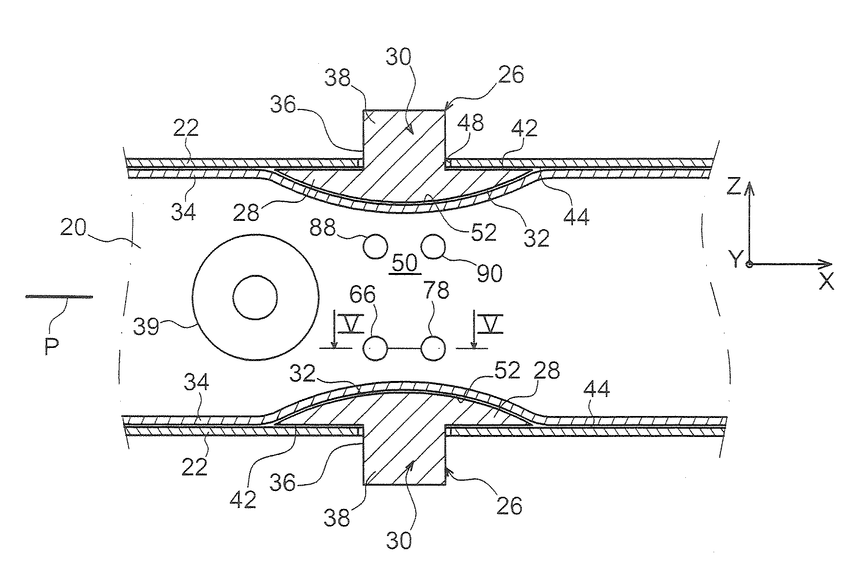
[0034]With reference to FIG. 1, the figure shows an aircraft engine assembly 1 designed to be fixed under a wing 3 of this aircraft (not shown), this assembly 1 according to one preferred embodiment of this invention being provided with an attachment pylon 4.

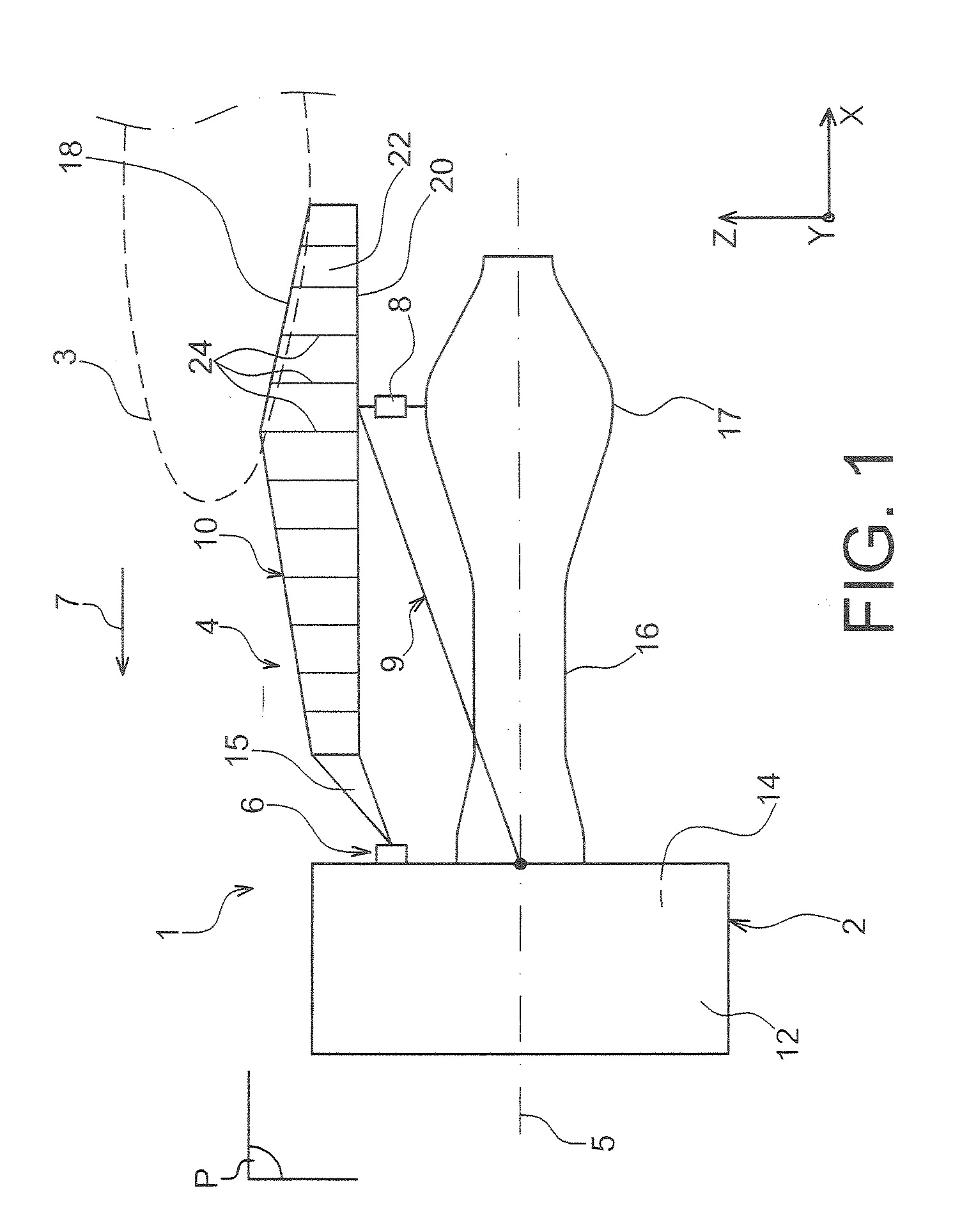
[0035]Globally, the engine assembly 1 comprises an engine such as a turbojet 2 and the attachment pylon 4, the attachment pylon in particular being provided with a plurality of engine attachments 6, 8 and 9, and a rigid structure 10 to which these attachments are fixed. For guidance, note that the assembly 1 is designed to be surrounded by a pod (not shown) and that the attachment pylon 4 comprises another series of attachments (not shown) to assure suspension of this assembly 1 under the aircraft wing.

[0036]Throughout the following description, by convention, X refers to the longitudinal direction of the pylon 4 that is also considered to be the same as the longitudinal direction of the turbojet 2, this direction X being parall...


PUM


Abstract

An engine attachment pylon for an aircraft including an aft engine attachment fitted with an aft attachment body and two lateral brackets each including a longitudinal portion in contact with an inner face of the lateral panel associated with it and mounted fixed on the same inner face, and a transverse portion including an attachment interface for the aft attachment body, the transverse portion configured to pass through a recess formed on the associated lateral panel.

Description

TECHNICAL DOMAIN[0001]This invention relates in general to an engine attachment pylon for an aircraft such as a turbojet. This type of attachment pylon is also called an EMS (Engine Mounting Structure), that can be used to suspend the turbojet below the aircraft wing, or to fit this turbojet above the same wing, through a plurality of engine attachments.STATE OF PRIOR ART[0002]Such an attachment pylon is designed to form an attachment interface between an engine such as a turbojet and an aircraft wing. It transmits forces generated by its associated turbojet to the structure of this aircraft, and it also enables routing of fuel, electrical, hydraulic and air systems between the engine and the aircraft.[0003]In order to transmit forces, the pylon comprises a rigid structure, frequently of the “box” type, in other words formed by the assembly of upper and lower spars and two lateral panels connected to each other through transverse ribs.[0004]The pylon is also provided with a mounting...

Claims


Application Information

Patent Timeline
IPC IPC(8): B64D27/00
CPCY02T50/44B64D27/26Y02T50/40
Inventor COMBES, STEPHANE
Owner AIRBUS OPERATIONS SAS
Why Eureka
Try Eureka