Coil unit, method of manufacturing the same, and electronic instrument

a technology of coil unit and coil body, which is applied in the direction of magnets, transformers/react mounting/support/suspension, magnetic bodies, etc., can solve the problems of transmission coil heat generation, non-contact power transmission, and metal induction heating or reduction in efficiency or induction heating of metals

Active Publication Date: 2008-08-21
138 EAST LCD ADVANCEMENTS LTD
View PDF10 Cites 22 Cited by
  • Summary
  • Abstract
  • Description
  • Claims
  • Application Information

AI Technical Summary

Problems solved by technology

Non-contact power transmission has a problem in that a transmission coil produces heat.
Therefore, when a metal is brought close to the magnetic field, the magnetic field is absorbed by the metal, whereby a decrease in efficiency or induction heating of the metal occurs.
This makes it difficult to utilize a metal optimum for heat dissipation.

Method used


Image

  • Coil unit, method of manufacturing the same, and electronic instrument
  • Coil unit, method of manufacturing the same, and electronic instrument
  • Coil unit, method of manufacturing the same, and electronic instrument

Examples


application example

[0121 of Electronic Instrument

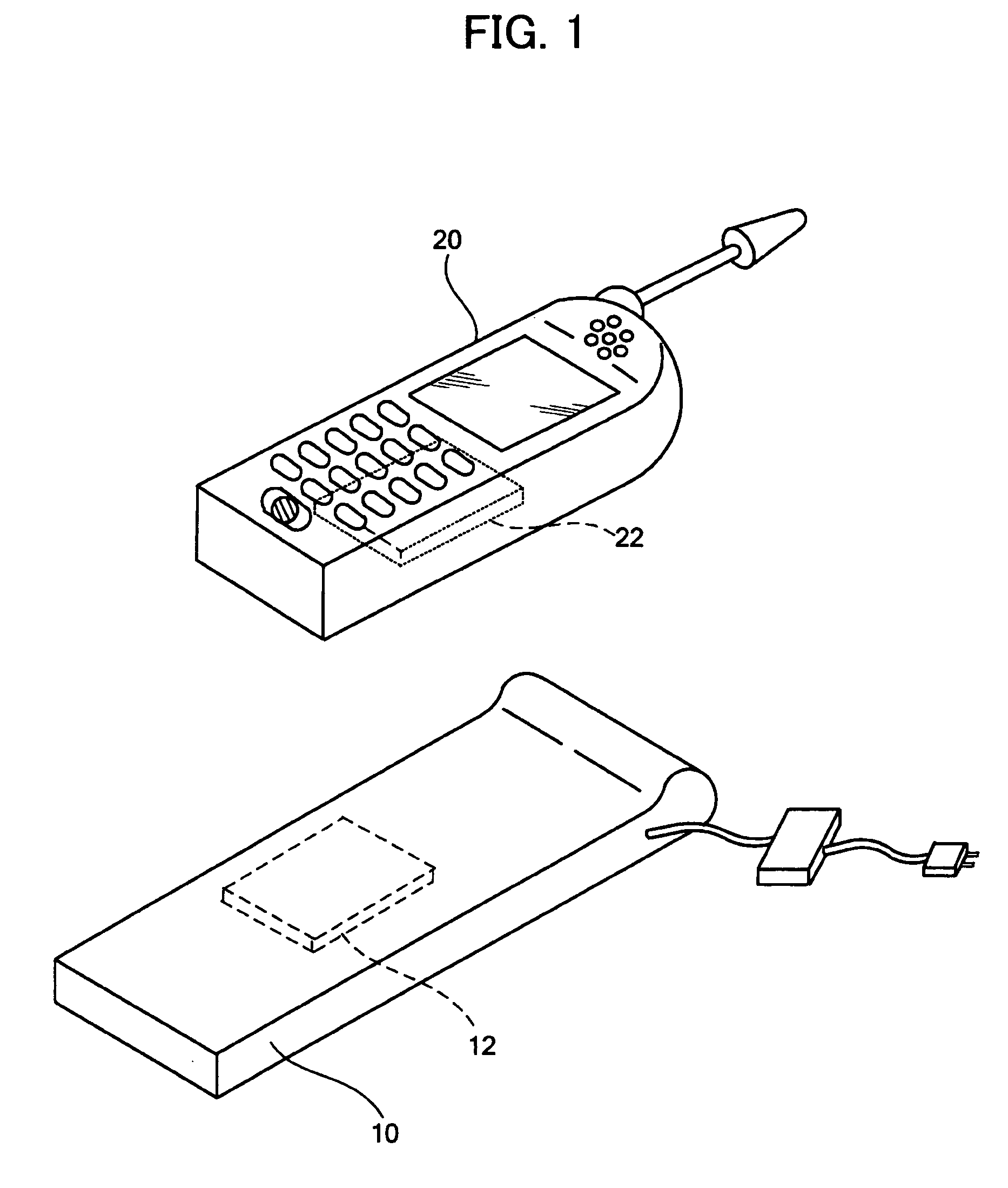
[0122]The above embodiments may be applied to an electronic instrument which performs power transmission or signal transmission. For example, the above embodiments may be applied to a charging target including a secondary battery (e.g., wristwatch, electric toothbrush, electric shaver, cordless telephone, personal handyphone, mobile personal computer, personal digital assistant (PDA), or power-assisted bicycle) and a charger which charges the charging target.

[0123]Although only some embodiments of the invention have been described in detail above, those skilled in the art would readily appreciate that many modifications are possible in the embodiments without materially departing from the novel teachings and advantages of the invention. Accordingly, such modifications are intended to be included within the scope of the invention. Any term cited with a different term having a broader meaning or the same meaning at least once in the specification and the ...


PUM

PropertyMeasurementUnit
magnetic fluxaaaaaaaaaa
conductiveaaaaaaaaaa
heightaaaaaaaaaa

Abstract

A coil unit includes a planar coil, a magnetic member that is provided under the planar coil, a magnetic flux leakage prevention member that is provided under the magnetic member, and a heat sink that is provided under the magnetic flux leakage prevention member. The magnetic flux leakage prevention member is electrically insulated from the heat sink. The magnetic flux leakage prevention member is insulated from the heat sink using a double-sided adhesive tape, for example. Since the heat sink dissipates heat generated from the planar coil and is electrically insulated from the magnetic flux leakage prevention member, the heat sink does not function as a member which receives a magnetic flux.

Description

[0001]Japanese Patent Application No. 2007-39885 filed on Feb. 20, 2007 and Japanese Patent Application No. 2007-325407 filed on Dec. 18, 2007, are hereby incorporated by reference in their entirety.BACKGROUND OF THE INVENTION[0002]The present invention relates to a coil unit relating to non-contact power transmission using a coil, a method of manufacturing the same, an electronic instrument, and the like.[0003]Non-contact power transmission has been known which utilizes electromagnetic induction to enable power transmission without metal-to-metal contact. As application examples of non-contact power transmission, charging a portable telephone, a household appliance (e.g., telephone handset), and the like has been proposed.[0004]Non-contact power transmission has a problem in that a transmission coil produces heat. Technologies which suppress such heat generation have been proposed. JP-A-8-103028 discloses a design method which suppresses heat generation during non-contact charging....

Claims


Application Information

Patent Timeline
Patent Type & Authority Applications(United States)
IPC IPC(8): H01F27/22H01F27/06H01F27/02H01F41/04H01F27/28
CPCH01F27/22H01F27/2804Y10T29/4902H01F38/14H01F27/365H01F27/36H01F27/363A47L1/15
Inventor HASEGAWA, MINORUKURODA, MASAO
Owner 138 EAST LCD ADVANCEMENTS LTD
Why Eureka
Try Eureka