Fastening divice

a technology of fastening and divice, which is applied in the direction of threaded fasteners, snap fasteners, screw fasteners, etc., can solve the problems of lack of tightness and unbalance of module support, and achieve the effect of simple and inexpensive manufacturing

Inactive Publication Date: 2008-08-28
TRW AUTOMOTIVE ELECTRONICS & COMPONENTS GMBH & CO KG
View PDF7 Cites 21 Cited by
  • Summary
  • Abstract
  • Description
  • Claims
  • Application Information

AI Technical Summary

Benefits of technology

[0004]It is an object of the present invention to provide a fastening device by which both the module support and also the panelling piece are jointly fastened in a detachable manner on the raw component of the vehicle, such as a door plate, and by which, through simplifying the working steps during the fastening of the module support and the inner panelling of the door, the installation time and therefore also the installation costs can be reduced.
[0006]In a preferred embodiment, the invention provides a multi-part fastening device having detent elements in the lower part of the fastening clip for fastening to the body of the vehicle, in particular for mounting in a bore of the raw component of the vehicle body, and having a mounting bore in the head part of the fastening clip comprising further detent elements for engaging with a pin-shaped fastening element which holds the door panelling. The module support part can be formed from plastic. The fastening device according to the invention makes multiple, non-destructive dismantling possible. In addition, by simplifying the working steps during the fastening of the module support and the door panelling, the installation time and therefore the installation costs are reduced.
[0010]The fastening clip and the module support part preferably form a pre-assembled unit so that the mounting of the assembly into the vehicle is significantly facilitated.
[0013]The fastening clip and the module support part are preferably formed from plastic. This contributes to simple and inexpensive manufacturing by injection molding. Finally, the fastening element for the panelling part can also have a head part comprising tolerance equalizing means.

Problems solved by technology

Through this type of fastening, an undulation of the module support can occur, from which a lack of tightness can result.

Method used


Image

  • Fastening divice
  • Fastening divice
  • Fastening divice

Examples


Embodiment Construction

)

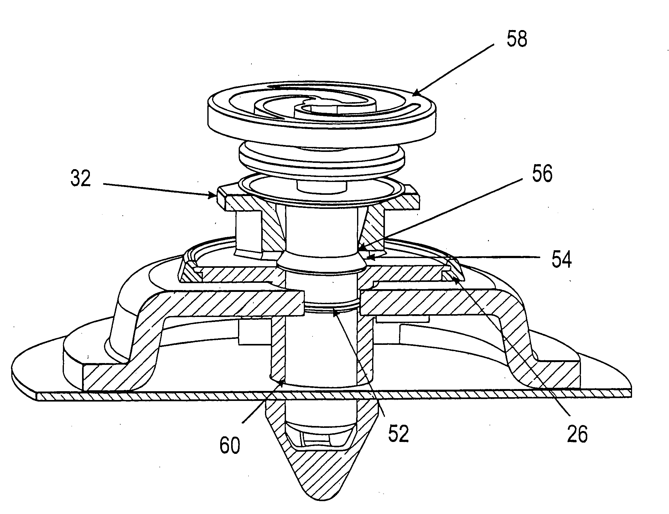
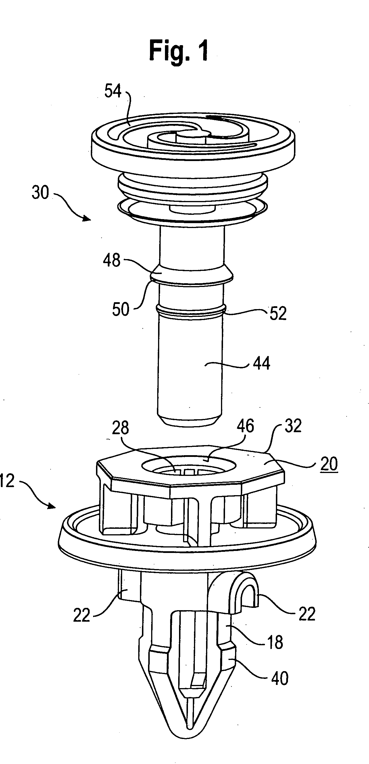
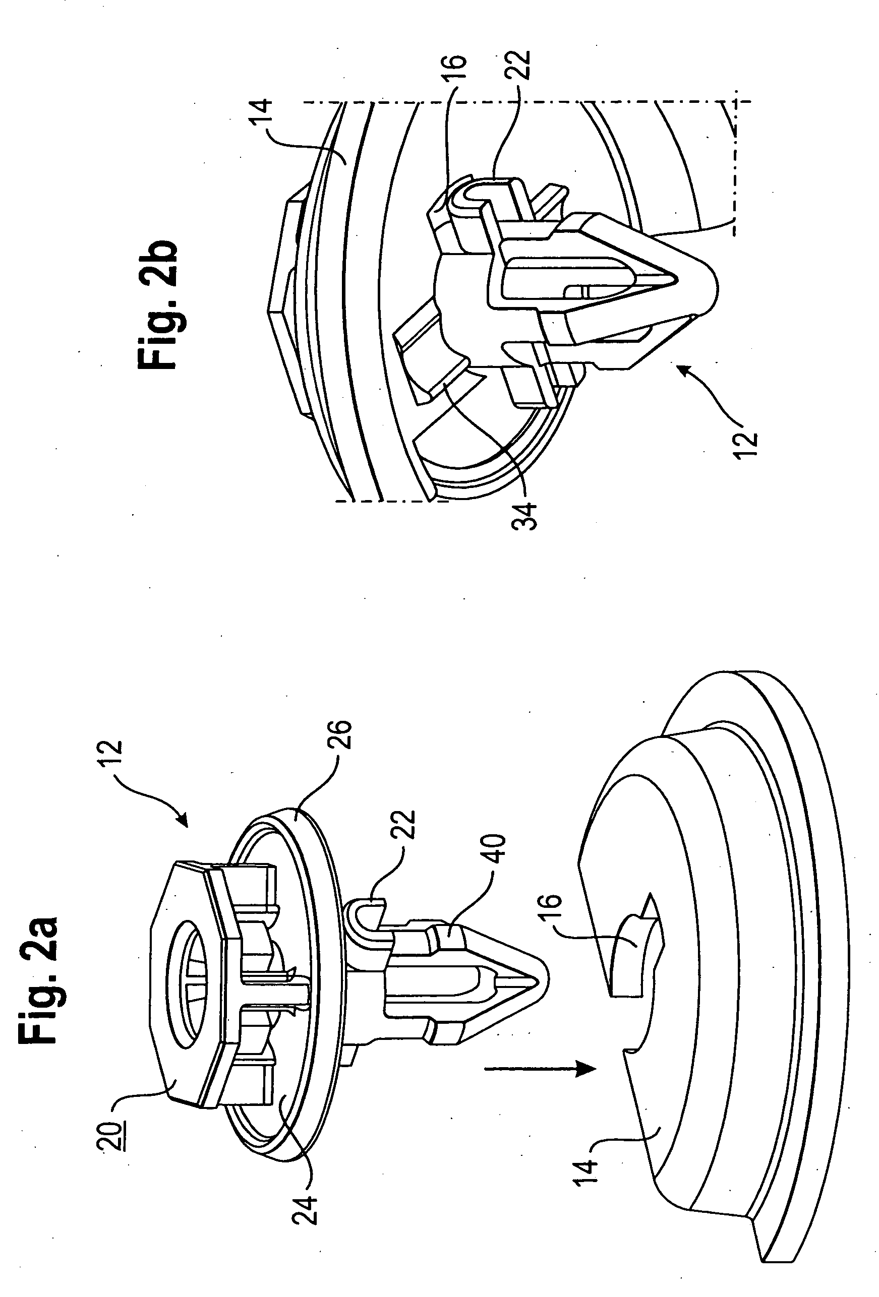
[0024]A preferred embodiment of the fastening device according to the invention is shown in the enclosed drawings, FIGS. 1 to 9. The fastening device according to the invention comprises a fastening clip 12 and a module support part 14. An opening 16 to receive the fastening clip 12 is provided in the module support part 14. The fastening clip 12 has a shaft 18 and a head part 20 which is formed onto the shaft. Beneath the head part 20, locking elements 22 are provided on the shaft 18, which engage into the opening 16 of the module support part 14 and secure the fastening clip 12 on the module support part 14 (FIGS. 1 to 3).

[0025]The locking elements 22 are preferably formed by one or more projections protruding radially from the shaft 18. The head part 20 of the fastening clip 12 may additionally have a disc-shaped element 24 with a circumferential seal 26. In the assembled state, the opening 16 of the module support 14 is sealed with the disc-shaped element and the encircling sea...


PUM


Abstract

A fastening device comprises a fastening clip (12) and a module support part (14) having an opening (16) to receive the fastening clip (12), wherein the fastening clip (12) has a shaft (18) and a head part (20) which is formed onto the shaft. Locking elements (22) are provided on the shaft (18) underneath the head part (20), which locking elements engage into the opening (16) of the module support part (14) and secure the fastening clip (12) on the module support part. The fastening device is used for fastening a module support and a panelling piece on a raw component such as a door plate of a motor vehicle.

Description

FIELD OF THE INVENTION[0001]The invention relates to a fastening device, in particular for fastening a module support and a panelling piece on a raw component such as a door plate of a motor vehicle.BACKGROUND OF THE INVENTION[0002]Module supports usually serve for the fastening of mechanical and / or electrical operating- and control modules which are integrated in a vehicle door, such as window levers for example. The module supports which are currently used are aluminium parts which are fastened to the raw component of the vehicle door with metal blind rivets. Through this type of fastening, an undulation of the module support can occur, from which a lack of tightness can result.[0003]The fastening of the inner door lining on the raw component of the vehicle door usually takes place by fastening elements which are mounted on the lining or panelling piece and which are detachably connected with the raw component.SUMMARY OF THE INVENTION[0004]It is an object of the present invention ...

Claims


Application Information

Patent Timeline
Patent Type & Authority Applications(United States)
IPC IPC(8): B42F1/00
CPCB60R11/00B60R11/02B60R13/0206B60R13/06Y10T24/44026F16B5/0642F16B19/1081F16B21/02B60R2011/0071B60R2011/0059F16B2/20
Inventor JATZKE, STEFAN
Owner TRW AUTOMOTIVE ELECTRONICS & COMPONENTS GMBH & CO KG
Why Eureka
Try Eureka