

Small refractive zoom lens optical system
a technology of optical system and refractive zoom lens, which is applied in the field of small refractive zoom lens optical system, can solve the problems of lowering resolution and uniform resolution, and achieve the effects of high resolution, small size and high resolution
- Summary
- Abstract
- Description
- Claims
- Application Information
AI Technical Summary
Benefits of technology
Problems solved by technology
Method used
Image

Examples
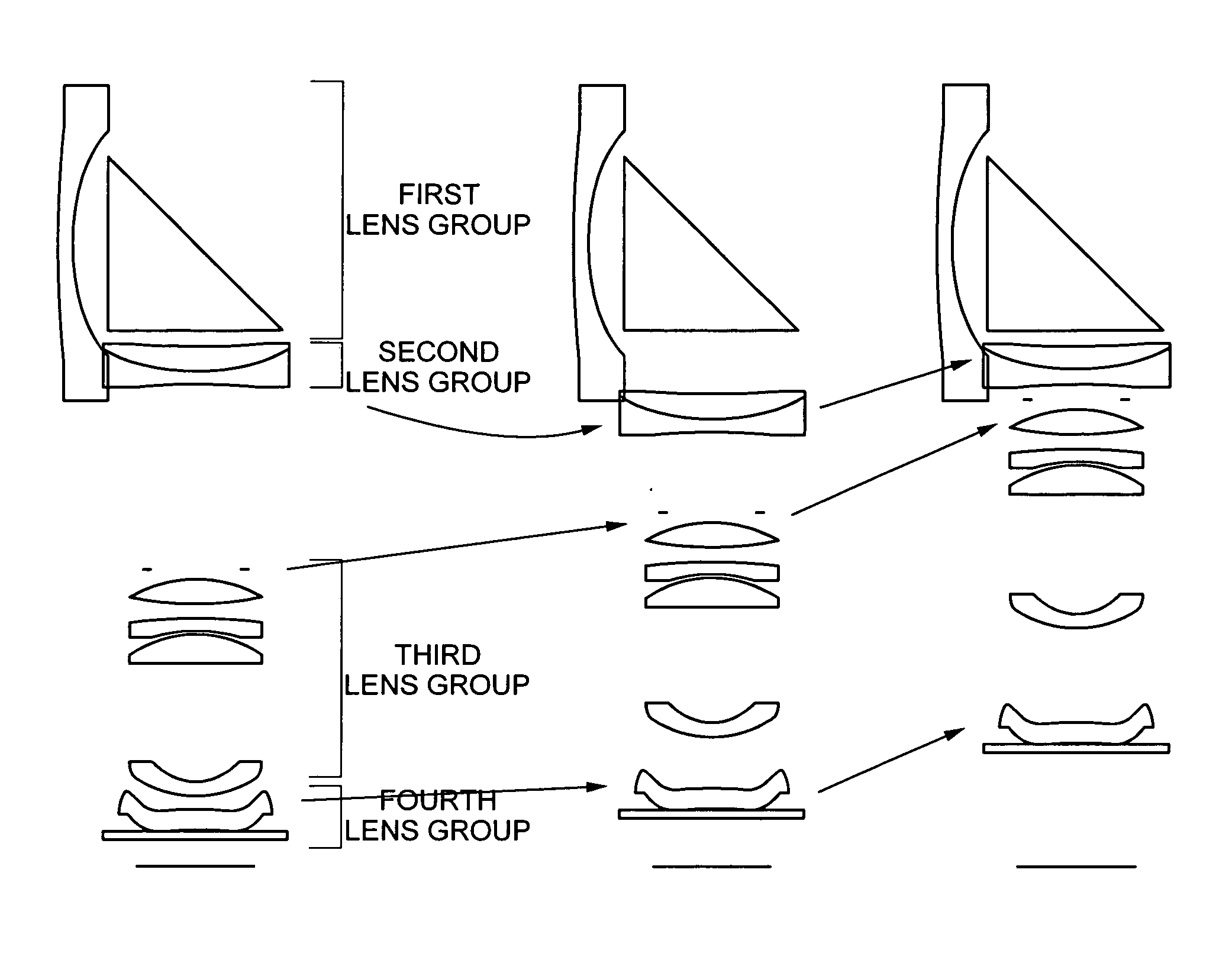
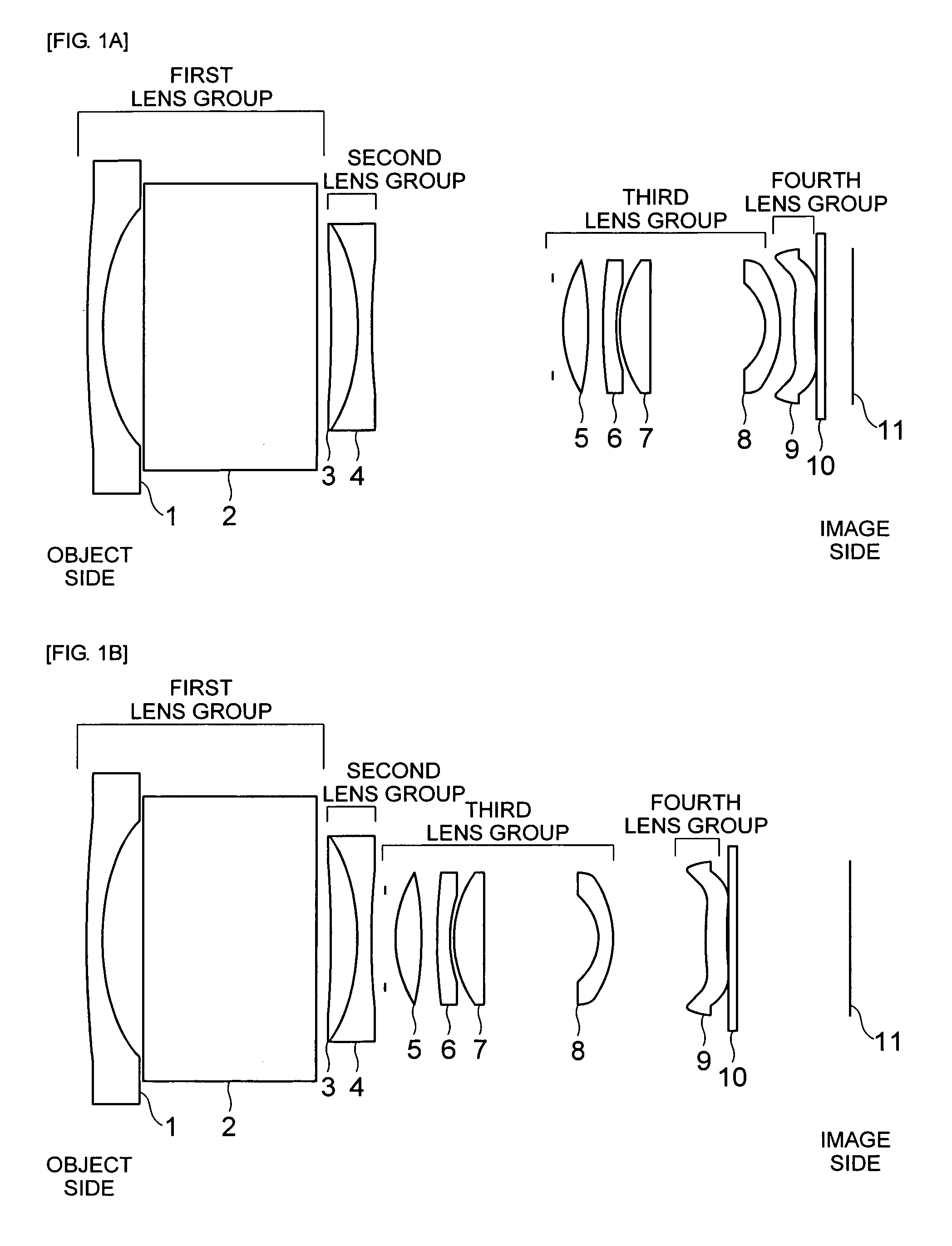
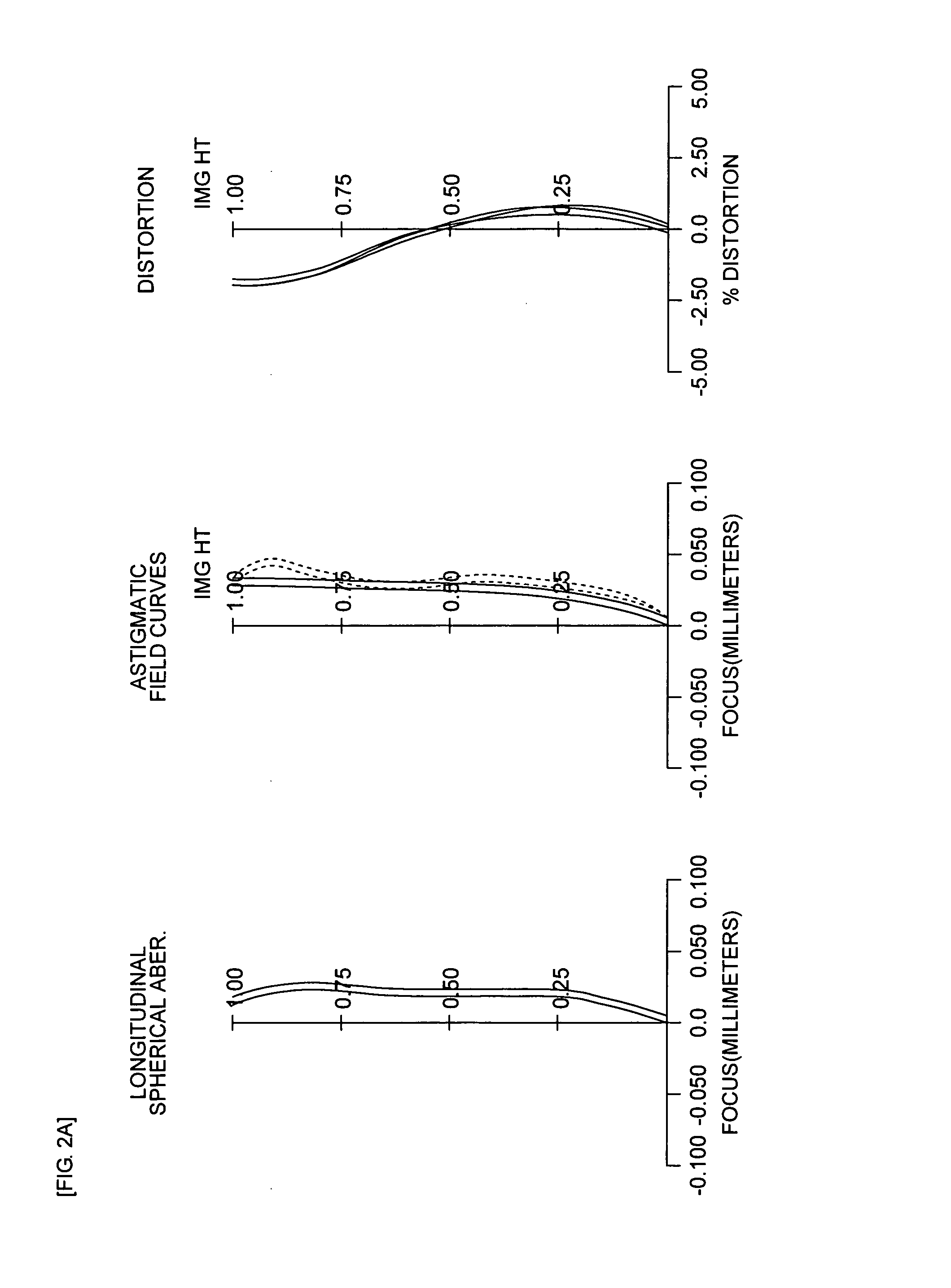
first embodiment
[0066]
TABLE 2Sur-faceSurfaceAper-#typeR valueD valueNdVdtureInfinityInfinity1Aspheric−4.93320.17831.544156.09surface2Aspheric8.25040.5163surface3Infinity2.24151.568856.044Infinity0.07035Infinity0.1117 (Z)6−11.91630.35691.846723.787−2.53770.17571.835042.98811.93982.3465 (Z)StopInfinity0.10540.583510Aspheric1.47620.33931.495380.940.6046surface11Aspheric−4.62890.1967surface128.40640.17571.846723.78132.58140.0442141.59770.38191.497081.611558.20911.495016Aspheric−1.00220.17571.544156.09surface17Aspheric−3.37930.1757 (Z)surface18Aspheric1.45950.25991.632223.43surface19Aspheric1.66320.0351surface20Infinity0.000021Infinity0.10541.516864.2022Infinity0.3518 (Z)23Infinity0.02 (Z)
TABLE 3#1#2#10#11a1−1.000000000000E−00 1.000000000000E+007.139063600000E−01−1.000000000000E+00a32.035645148380E+021.509233883250E−021.142833970130E−02 1.433668349570E+02843.780374687410E+013.376424155450E+01−2.134583004690E+01 −7.716000377580E−02a5−5.186333476160E−01 −5.018507025500E−01 7.481268216540E−01 2.83285479312...
second embodiment
[0068]
TABLE 5Sur-faceSurfaceAper-#typeR valueD valueNdVdtureInfinityInfinity1Aspheric−8.37340.17861.544156.09surface2Aspheric5.12240.5172surface3Infinity2.21521.834037.354Infinity0.07145Infinity0.4161 (Z)6−5.63510.30111.846723.787−2.53350.17861.713053.94811.78902.1866 (Z)StopInfinity0.12030.607110Aspheric1.37490.43441.495380.940.6357surface11Aspheric−2.75500.0357surface12−5.84400.17861.846723.781317.16410.0357144.34620.29081.497081.6115−8.54331.789716Aspheric−0.96640.17861.544156.09surface17Aspheric−2.40290.1739 (Z)surface18Aspheric1.60540.28571.544156.09surface19Aspheric1.61240.0000surface20Infinity0.000021Infinity0.10711.516864.2022Infinity0.3571 (Z)23Infinity0.0189 (Z)
TABLE 6#1#2#10#11a11.500000000000E+00−5.000000000000E+00−4.558805600000E−01 −2.000000000000+00a3−4.889706461500E−00 −6.339288529670E−025.882515397310E−03 9.998497048000E−03a44.505117039260E+01 5.142043876800E+01−1.220028126600E−01 −1.437072465730E−01a5−6.560399050430−01 −5.893467398020E−015.624244210140E−01 3.878109...
PUM
 Abstract
Description
Claims
Application Information