High efficiency, peak-power reducing, domestic hot water heater

a technology of high efficiency and peak power, which is applied in the direction of fluid heaters, electric heating, electrical equipment, etc., can solve the problems of high instantaneous demand at re-activation, high instantaneous demand of power on the electrical distribution network, and high cost of utilities, so as to reduce the amount of hot water, reduce the propagation of harmful bacteria, and reduce the kilowatt demand of domestic hot water heaters

Inactive Publication Date: 2008-08-28
LESAGE CLAUDE +1
View PDF8 Cites 28 Cited by
  • Summary
  • Abstract
  • Description
  • Claims
  • Application Information

AI Technical Summary

Benefits of technology

[0011]According to still another embodiment, there is provided a method of reducing the kilowatt demand of a domestic hot water heater during peak hour periods without reducing the amount of hot water requested by a user using a large volume of hot water between 90 to 220 liters from a hot water tank having a predetermined water holding capacity of 180 or 270 liters. The method comprises the steps of providing a hot water tank with three spaced-apart electrical resistive heating elements extending therein in a spaced-apart manner. The bottom one of the resistive heating elements has a low watt density rating in the ...

Problems solved by technology

During peak hours when hot water is used, normally between 6:00 a.m. and 9:00 a.m. and 6:00 p.m. to 9:00 p.m., there is an excessive demand of power on the electrical distribution netwo
mers. These solutions are, however, costly to the utilities and are not popular with consu
mers. They also cause very high instantaneous demand at re-activation if too many units are turned back on at the ...

Method used


Image

  • High efficiency, peak-power reducing, domestic hot water heater
  • High efficiency, peak-power reducing, domestic hot water heater
  • High efficiency, peak-power reducing, domestic hot water heater

Examples


Embodiment Construction

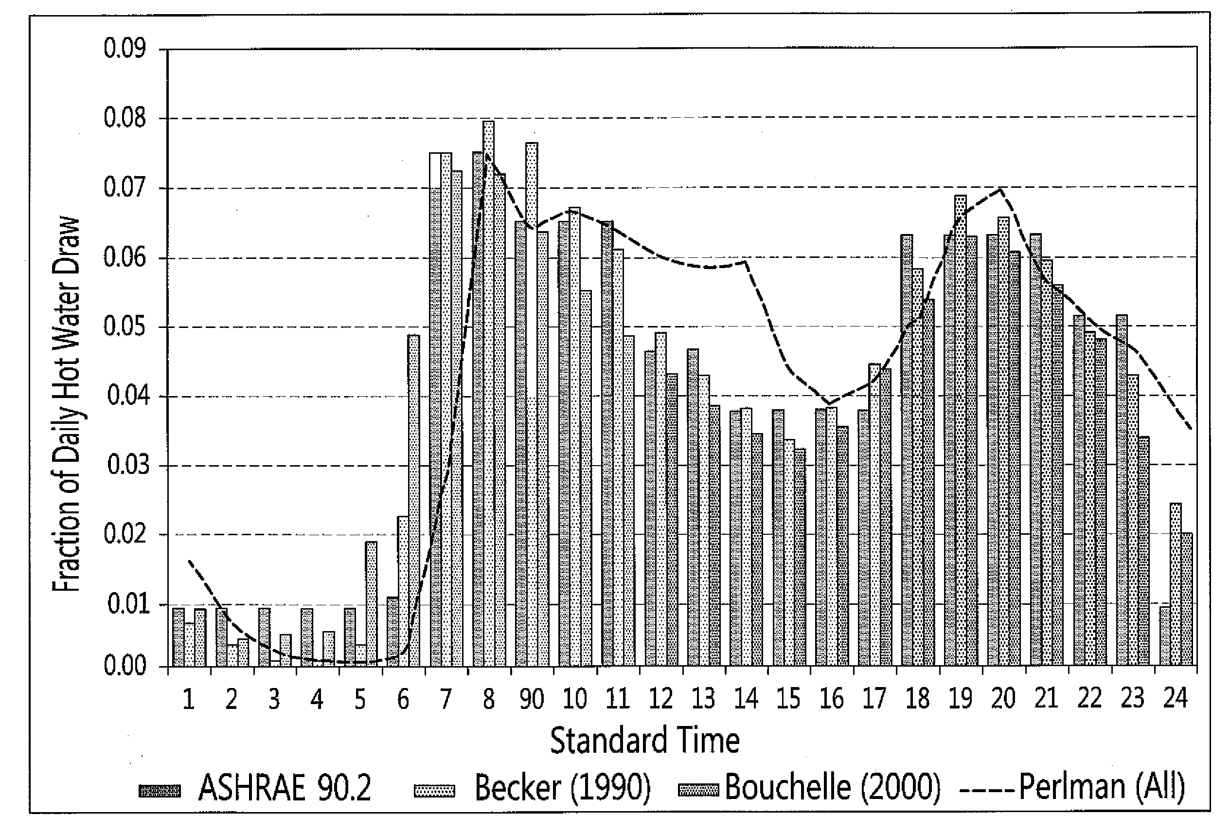
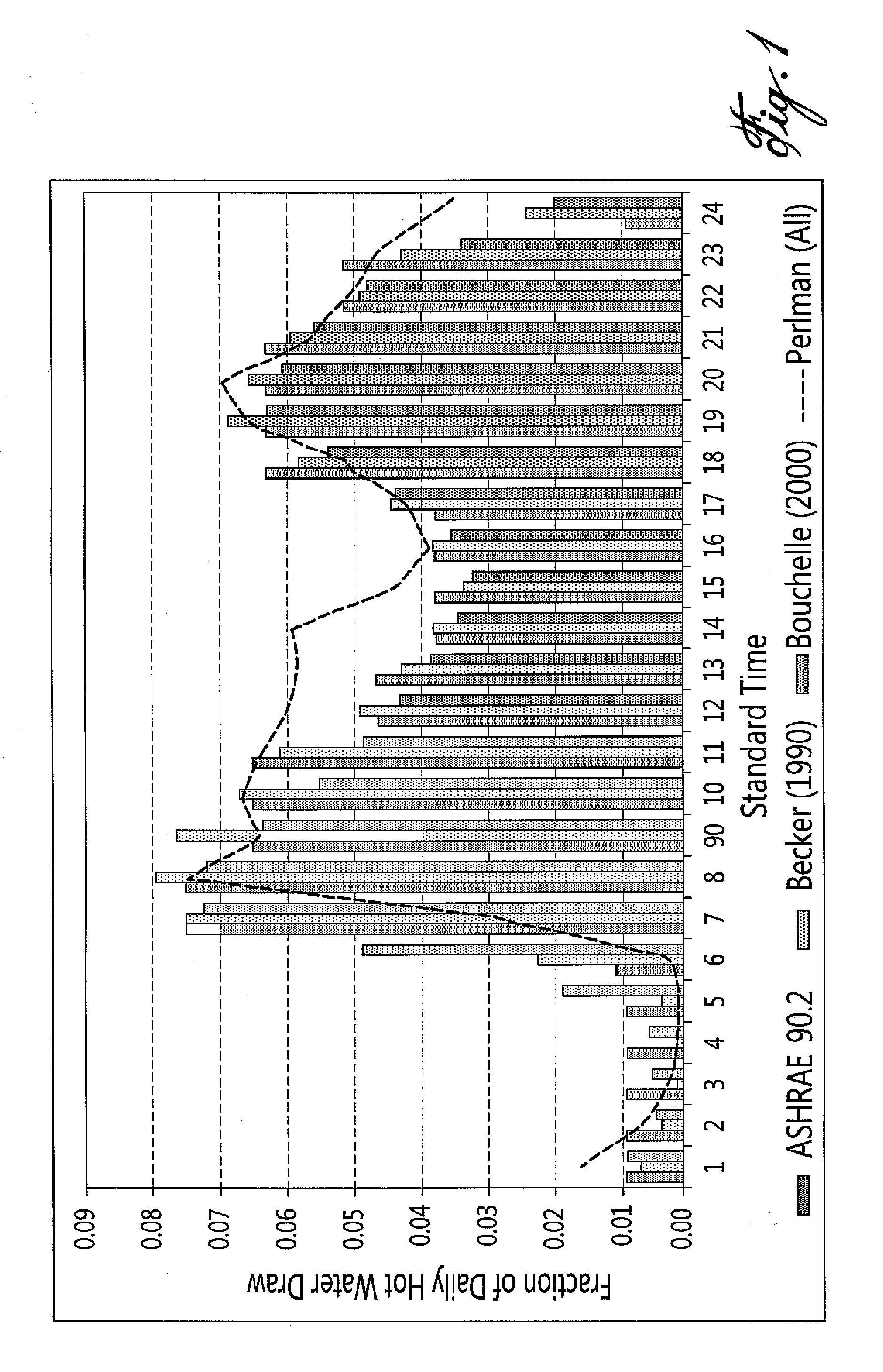
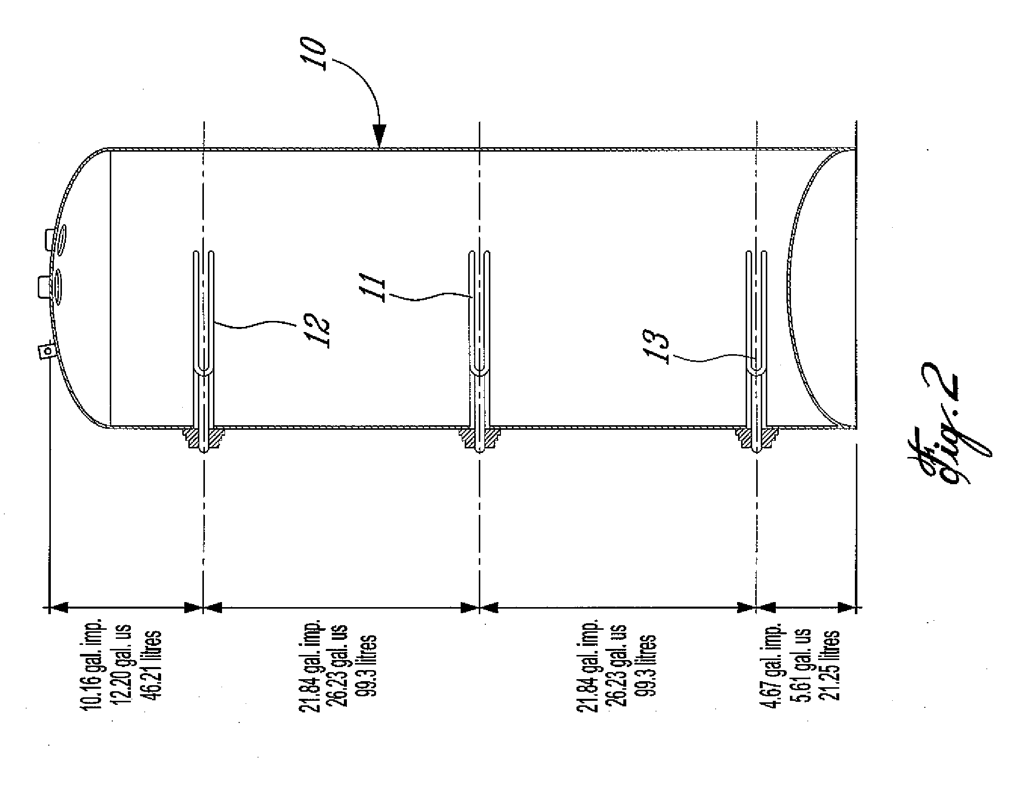
[0032]Although it is stated in the above referred-to U.S. patent that any size of tank can be used, one must be careful in the actual position of the elements in order to insure that end users do not run out of hot water and that the intermediate element does not activate unless absolutely necessary. Furthermore, it is not recommendable that the actual size of the tank be less than 270 liters in cold climate geographical areas due to the fact that a smaller tank will not provide the appropriate amount of hot water requested by a user during peak periods. Warmer climates where tank inlet water temperatures are higher than in northern areas of North-America, could most likely allow smaller volume tanks such as 180 liters. Nonetheless, hot water drawing trends must be looked at. As such, the following table exposes figures of the average hot water consumption. These were taken from ASHRAE Standard.

Average Hot Water Use, LHourlyDailyWeeklyMonthlyGroupOVLPeakOVLPeakOVLPeakOVLPeakAll fami...


PUM


Abstract

There is herein described a peak-power reducing domestic hot water heater comprising: a closed tank having a predetermined water holding capacity, a hot water outlet in a top end wall of said tank, a cold water inlet in a side wall of said tank adjacent a bottom wall thereof, three spaced apart resistive heating elements projecting substantially horizontally in said tank, each of said resistive heating elements having a temperature sensing element to enable a control of their respective activation; a bottom one of said resistive heating elements extending in said tank spaced slightly above said bottom wall and having a lowest power rating, said bottom resistive heating element being turned on when water is flowing into said cold water inlet and drawn out of said hot water outlet during a peak-power demand time period; a middle one of said resistive heating elements extending in said tank at a level which is calculated to be equal or above an average maximum daily water consumption volume drawn out during the peak power demand time periods; and a top one of said resistive heating elements extending between said middle element and said top end wall of said tank and having a highest power rating; said middle and said bottom resistive heating elements being activated simultaneously only when said top resistive heating element is inactive.

Description

CROSS-REFERENCE TO RELATED APPLICATIONS[0001]This patent application is a Continuation-In-Part of U.S. patent application Ser. No. 11 / 556,798, entitled “High efficiency, peak-power reducing, domestic hot water heater” filed on Nov. 6, 2006.TECHNICAL FIELD[0002]The present invention relates to a high efficiency, peak-power reducing, domestic hot water heater provided with three resistive heating elements.BACKGROUND ART[0003]In U.S. Pat. No. 4,948,948, there is described a water heater with multiple heating elements having different power factors and wherein these elements are controlled by a control circuit so that the elements are switched on at different periods of a day, outside peak hours, in order to reduce the power loads on an electrical distribution network during peak electrical power demand periods.[0004]During peak hours when hot water is used, normally between 6:00 a.m. and 9:00 a.m. and 6:00 p.m. to 9:00 p.m., there is an excessive demand of power on the electrical distr...

Claims


Application Information

Patent Timeline
IPC IPC(8): F24H1/20
CPCF24H9/2021F24H1/202
Inventor LESAGE, CLAUDELESAGE, JEAN-CLAUDE
Owner LESAGE CLAUDE
Why Eureka
Try Eureka