Inlaid Decorative Panels

a technology of decorative panels and inlay materials, applied in the field of decorative panels, can solve the problems of affecting the appearance of decorative panels, significant limitations on the stability of inlay materials positioned within the opening, and unsuitable for other uses than flooring

Inactive Publication Date: 2008-08-28
GREEN LAKE INVESTORS
View PDF16 Cites 24 Cited by
  • Summary
  • Abstract
  • Description
  • Claims
  • Application Information

AI Technical Summary

Benefits of technology

[0009]Thus, according to a first aspect of the present invention, an inlay for a decorative panel is formed within a suitable substrate material by forming a pocket within a rear surface of the substrate material. Once the pocket is formed, an opening or openings corresponding to the design to be utilized for the inlay is then cut into the front surface through the remaining portion of the substrate opposite the pocket such that the inlay opening and the pocket communicate with one another and extend completely through the substrate. A filler material is then positioned within the pocket flush with the rear surface of the su

Problems solved by technology
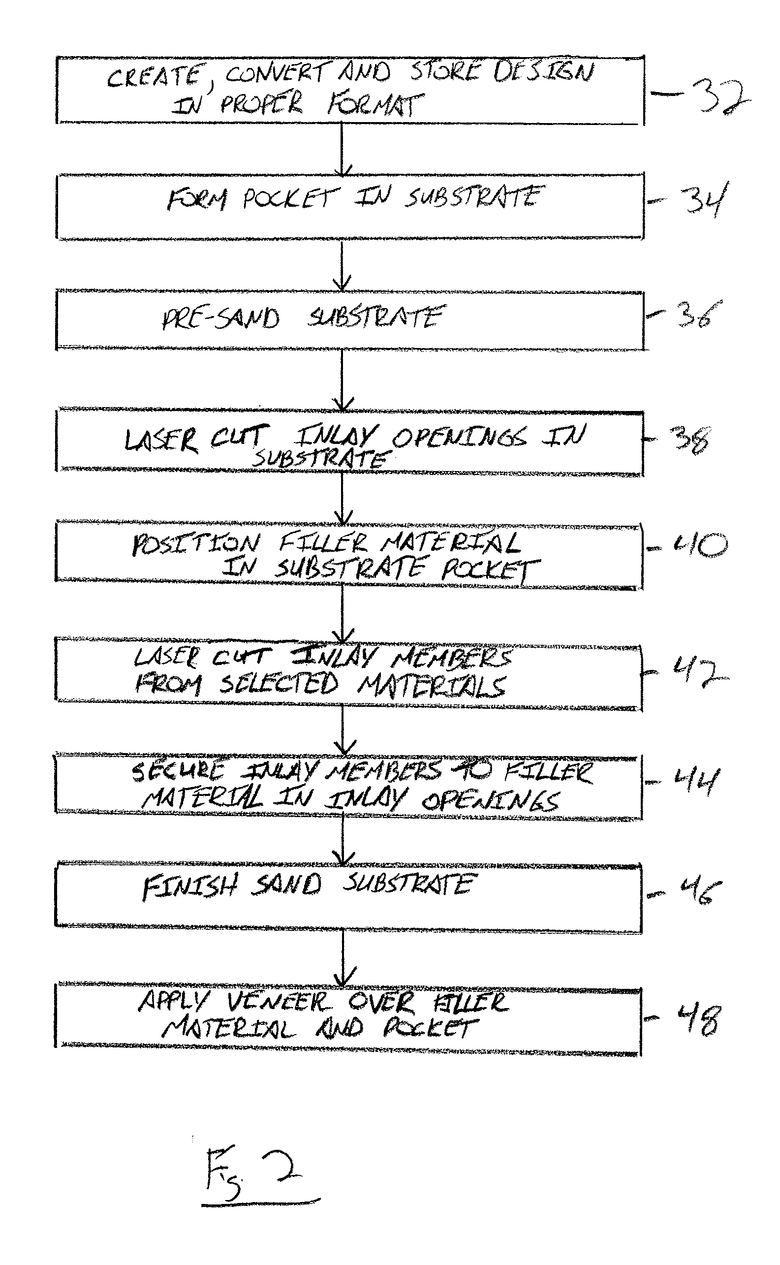
One significant shortcoming with decorative material constructions of this type is that the opening formed through the entire substrate creates significant limitations on the stability of the inlay materials positioned within the opening.
However, this thickness can often detract from the appearance of the substrate along its side edges, making it unsuitable for uses other than flooring where only the top surface is exposed.
This requires that the inlay material often be cut not only to form the particular design, but also to have the sam

Method used


Image

  • Inlaid Decorative Panels
  • Inlaid Decorative Panels
  • Inlaid Decorative Panels

Examples


Embodiment Construction

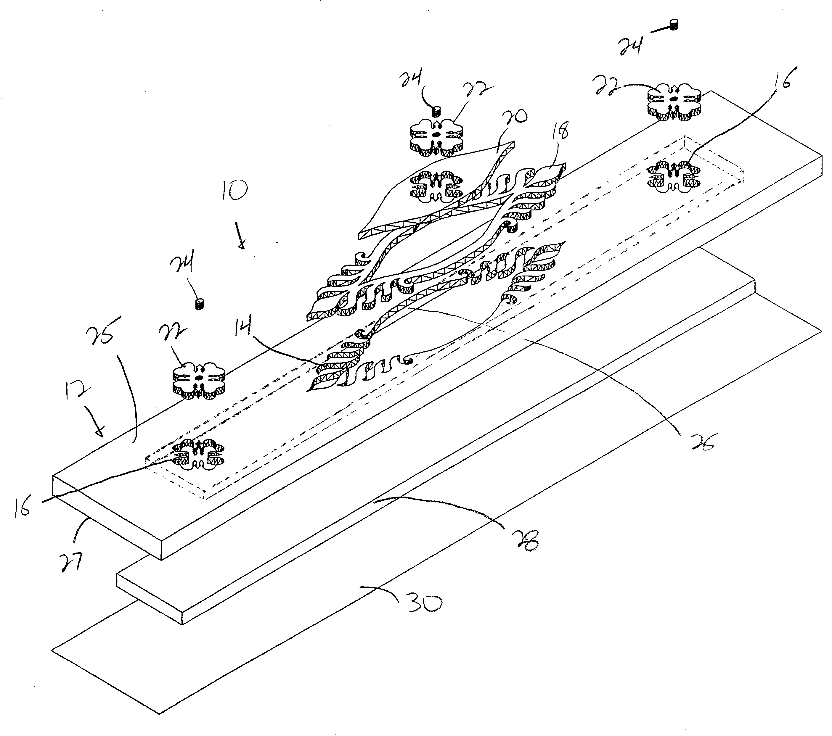
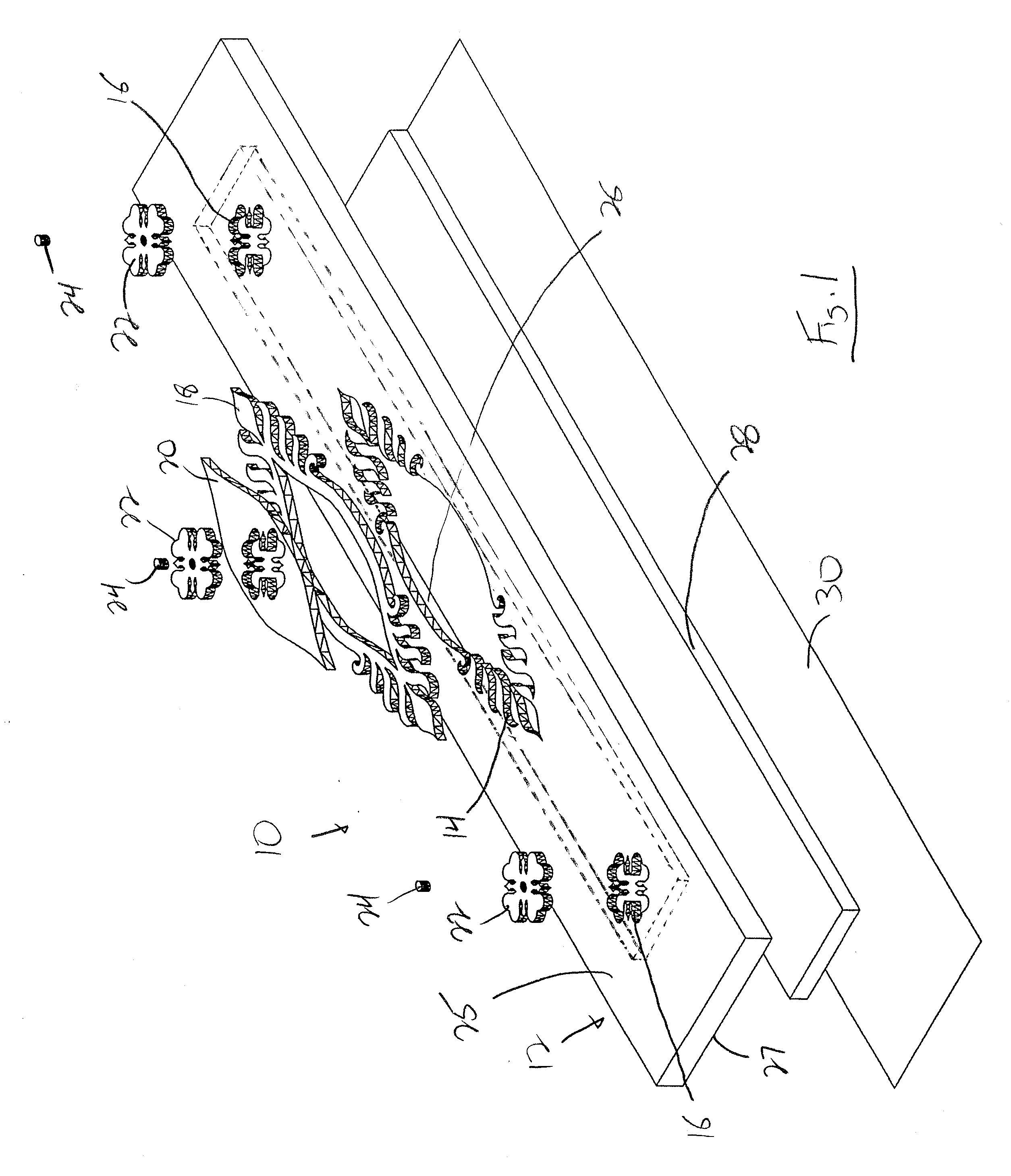
[0016]With reference now to the drawing figures in which like reference numerals designate like parts throughout the disclosure, a decorative panel constructed according to the present invention is indicated generally at 10 in FIG. 1. The panel 10 includes a substrate 12 formed of any suitable material, such as wood, stone, metal, or plastic, among others. The panel 10 can be designed for use in a flooring surface, as a step, a door, or as a cabinet panel, among other potential uses for the panel 10.

[0017]The substrate 12 for the panel 10 includes one or more inlay openings 14, 16 formed therein in which are positioned a number of inlay members 18-24, which may also have inlay openings formed in them. The substrate 12 may also have various other decorative features (not shown) formed on the substrate 12, such as beveled edges (not shown), glass panels (not shown) or carved designs (not shown), among others. The inlay openings 14, 16 extend partially through the substrate 12 from a f...


PUM

PropertyMeasurementUnit
Thicknessaaaaaaaaaa
Sizeaaaaaaaaaa
Areaaaaaaaaaaa

Abstract

The present invention is a decorative panel formed with an inlay design created by forming a number of inlay openings within a substrate for the panel by laser cutting the openings in the substrate. The openings are formed in communication with a pocket that is formed in the substrate opposite the inlay openings, such that the inlay openings and the pocket extend completely through the substrate. The pocket enables a piece of a filler material to be positioned within a pocket to form an appropriate backing for the inlay members which are positioned in the inlay openings and securely attached to the filler material.

Description

CROSS-REFERENCE TO RELATED APPLICATION[0001]This application claims priority from U.S. Provisional Application Ser. No. 60 / 856,207, filed on Nov. 2, 2006, which is expressly incorporated by reference herein in its entirety.FIELD OF THE INVENTION[0002]The present invention relates to decorative panels, and more specifically to decorative panels including inlaid designs or patterns therein.BACKGROUND OF THE INVENTION[0003]Decorative panels or other decorative surfaces are utilized in a wide variety of situations within both residential and commercial environments to provide a more aesthetically pleasing appearance to the environment. In a number of these environments, the decorative aspect of the panel is formed within the panel itself, such as by carving a decorative pattern directly into the panel. In other situations, the decorative aspect or piece of the panel is formed separately and secured to the exterior of the panel, such as by securing the decorative piece to the exterior of...

Claims


Application Information

Patent Timeline
IPC IPC(8): B44C1/26B32B37/00
CPCB44C1/26Y10T156/1052Y10T428/22B44C5/04
Inventor KENT, RICHARDSKALETSKI, BENNETTSCHUMACHER, LANCEDERENGOWSKI, ANDREW
Owner GREEN LAKE INVESTORS
Why Eureka
Try Eureka