Device and method for stabilising the flow through a chamber

Active Publication Date: 2008-09-04
LONZA COLOGNE
View PDF6 Cites 16 Cited by
  • Summary
  • Abstract
  • Description
  • Claims
  • Application Information

AI Technical Summary

Benefits of technology

[0015]Furthermore, the device according to the invention may have a housing, with the openings of the output and input channels being on the surface or outside of the housing for safety reasons. This design ensures that a person operating the device cannot or does not have to reach into the interior of the housing in which the electrodes and other possibly electrically charged components are located. In such a device, connecting of a reservoir and a collection tank is therefore be accomplished without risk. For practical reasons, the ports of both channels should be located on the same side of the housing, preferably the forward or front side, to facilitate handling of the device of the invention.
[0016]In addition to the measures

Problems solved by technology

The treatment of, in particular, living cells with electrical current or the feeding of the same through an electrical field always results in

Method used


Image

  • Device and method for stabilising the flow through a chamber
  • Device and method for stabilising the flow through a chamber
  • Device and method for stabilising the flow through a chamber

Examples


Example

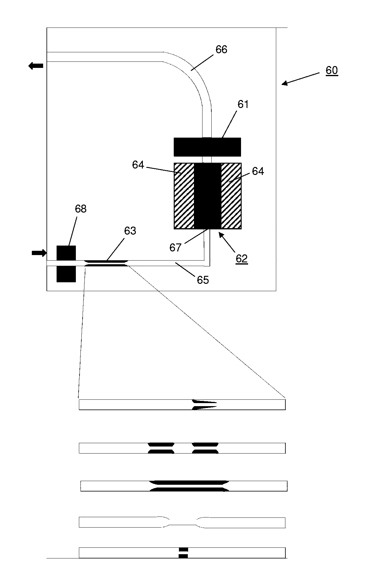
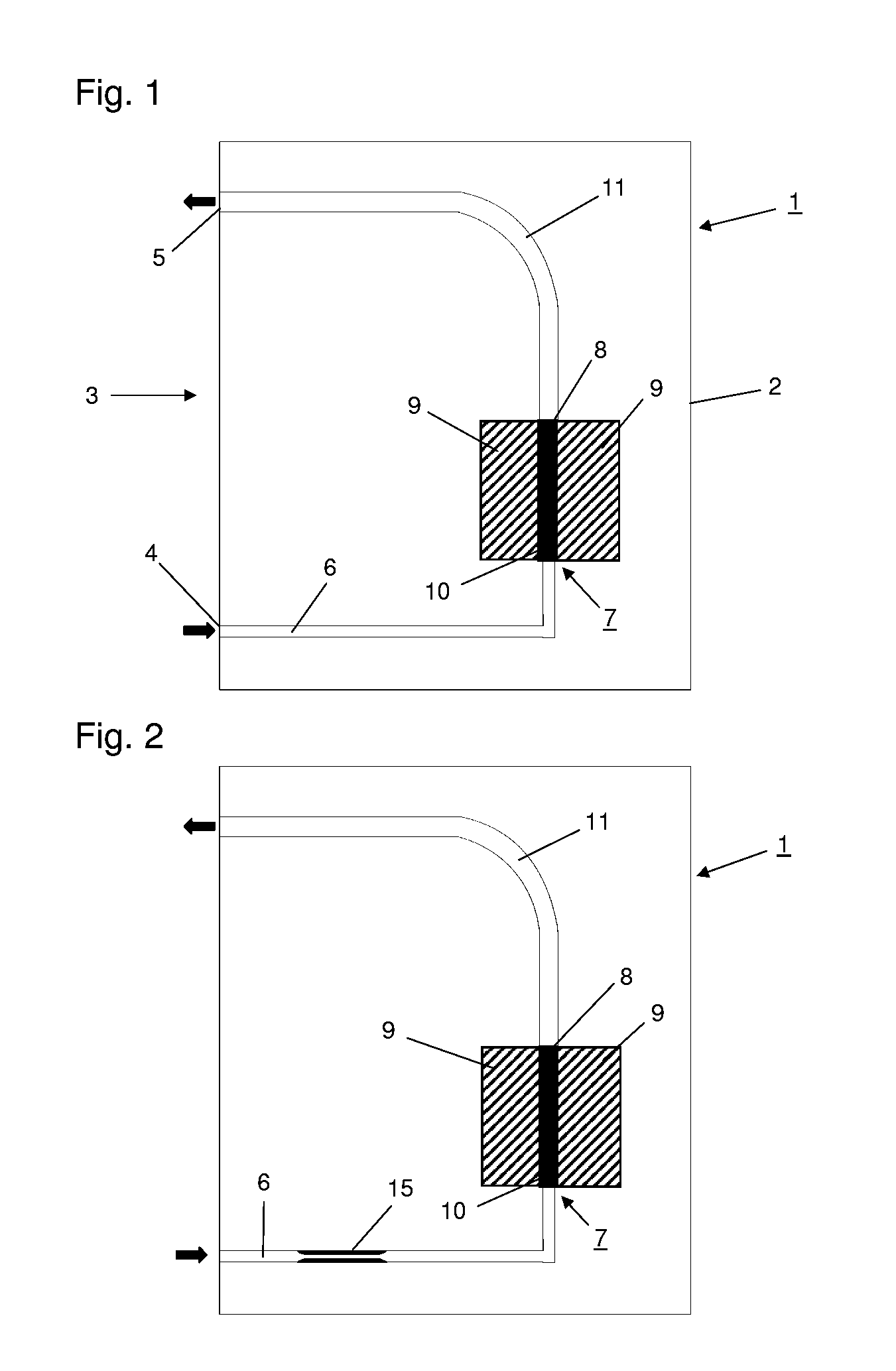
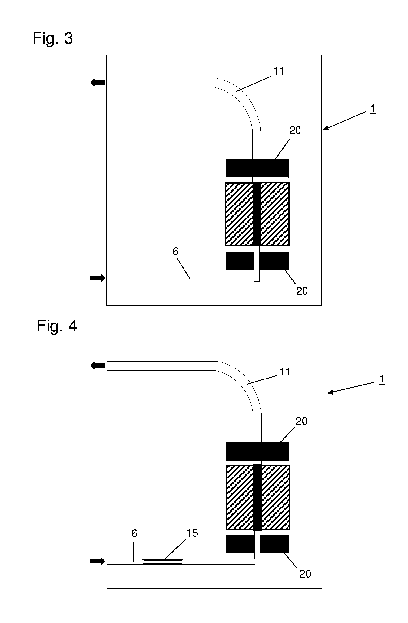
[0031]FIG. 1 shows a longitudinal section through an exemplary embodiment of the device according to the invention. Device 1 comprises a housing 2 which has 2 ports 4, 5 on its front side 3. Vessels can be connected to ports 4, 5, preferably by tubes or other lines, which each serve to receive a fluid. For example, a storage vessel or reservoir, from which the fluid is introduced into input channel 6 of device 1, preferably by means of a pump or compressed air, can be connected to port 4 (The arrows at ports 4, 5 indicate the direction of flow of the fluid). The fluid is then fed through input channel 6 into a chamber 7, which has two electrodes which are in contact with interior 10 of chamber 7. Of the electrodes, only electrode 8, arranged behind interior 10 of chamber 7, is visible in this representation, whilst the second electrode, which is arranged plane parallel to electrode 8, lies in front of the plane of intersection. The two electrodes are separated from each other by two...


PUM

PropertyMeasurementUnit
Thicknessaaaaaaaaaa
Flow rateaaaaaaaaaa
Diameteraaaaaaaaaa

Abstract

A device 1 with at least one electrode 8 for generating an electrical field in a chamber 7 is disclosed. The device 1 comprises at least one input channel 6 for introducing a fluid into the chamber 7, and at least one output channel 11 for discharging the fluid from the chamber 7. Also disclosed is a method for stabilising the flow of a fluid through a chamber 7 in which an electrical field is generated and which has at least one input channel 6 for introducing the fluid into the chamber and at least one output channel 11 for discharging the fluid from the chamber 8. To avoid undesirable backflow of the fluid due to gas formation, the average inside diameter of the input channel 6 of device 1 is smaller than the average inside diameter of the output channel 11.

Description

CROSS-REFERENCE TO RELATED APPLICATIONS[0001]This application claims the benefit of U.S. provisional application 60 / 891,266, filed Feb. 23, 2007, which is incorporated herein by reference in its entirety. This application claims priority from European application EP 07 003 739.5, also filed on Feb. 23, 2007.FIELD OF THE INVENTION[0002]The invention relates to a device with at least one electrode for generating an electrical field in a chamber, at least comprising at least one input channel for introducing a fluid into the chamber, and at least one output channel for discharging the fluid from the chamber. The invention also relates to a method for stabilising the flow of a fluid through a chamber in which an electrical field is generated and which has at least one input channel for introducing the fluid into the chamber and at least one output channel for discharging the fluid from the chamber.BACKGROUND OF THE INVENTION[0003]The introduction of biologically active molecules, for ex...

Claims


Application Information

Patent Timeline
IPC IPC(8): C12N13/00B01J19/08
CPCB01L3/5027G01N27/44756C12M35/02
Inventor WIRTH, ANDREASKAZINSKI, MICHAEL
Owner LONZA COLOGNE
Why Eureka
Try Eureka