Artificial eye socket system and method

a technology of artificial eye sockets and sockets, which is applied in the field of artificial eye sockets and methods for mounting artificial eyes, can solve the problems of inferior final product, less anatomically correct color and detail of surface paint, and more difficult to position and set anatomically correct eyes into fish head castings than it is to set other less anatomically correct eyes

Inactive Publication Date: 2008-09-11
TOHICKON CORP
View PDF10 Cites 5 Cited by
  • Summary
  • Abstract
  • Description
  • Claims
  • Application Information

AI Technical Summary

Benefits of technology

[0022]This invention is directed to an artificial eye socket and method for mounting artificial eyes. More specifically, this invention is directed to an apparatus, system and method and for mounting artificial eyes used in taxidermy, doll making and related applications. Such eyes may be adjusted during and, optionally, after the mounting process is completed to create a natural and realistic effect particularly when the artificial eye is made from a glass or glass-like substrate. In addition, when glass or glass-like artificial eyes are employed, the glass eye provides varying thicknesses of material which creates a more lifelike refraction of color.

Problems solved by technology

As mentioned above, as the artificial eyes which are produced become more anatomically correct, it becomes more difficult to position and set the anatomically correct eye into a fish head casting than it is to set other less anatomically correct eyes that are currently on the market.
In this regard, previous attempts at creating an eye socket for the mounting of artificial eyes did not have such a knife edge and, thus, the colors and details of the surface paint did not blend as well.
Furthermore, an unnatural gap between the artificial eye and the socket is often present with other eye socket devices thus producing an inferior final product.
In addition, no eye socket or socket system has been developed where the socket envelopes the eye so as not to require gluing.

Method used


Image

  • Artificial eye socket system and method
  • Artificial eye socket system and method
  • Artificial eye socket system and method

Examples


Embodiment Construction

[0041]It is to be understood that the figures and descriptions of the present invention have been simplified to illustrate elements that are relevant for a clear understanding of the present invention, while eliminating, for the purposes of clarity, many other elements which may be found in the present invention. Those of ordinary skill in the pertinent art will recognize that other elements are desirable and / or required in order to implement the present invention. However, because such elements are well known in the art, and because such elements do not facilitate a better understanding of the present invention, a discussion of such elements is not provided herein.

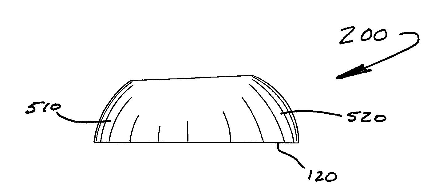
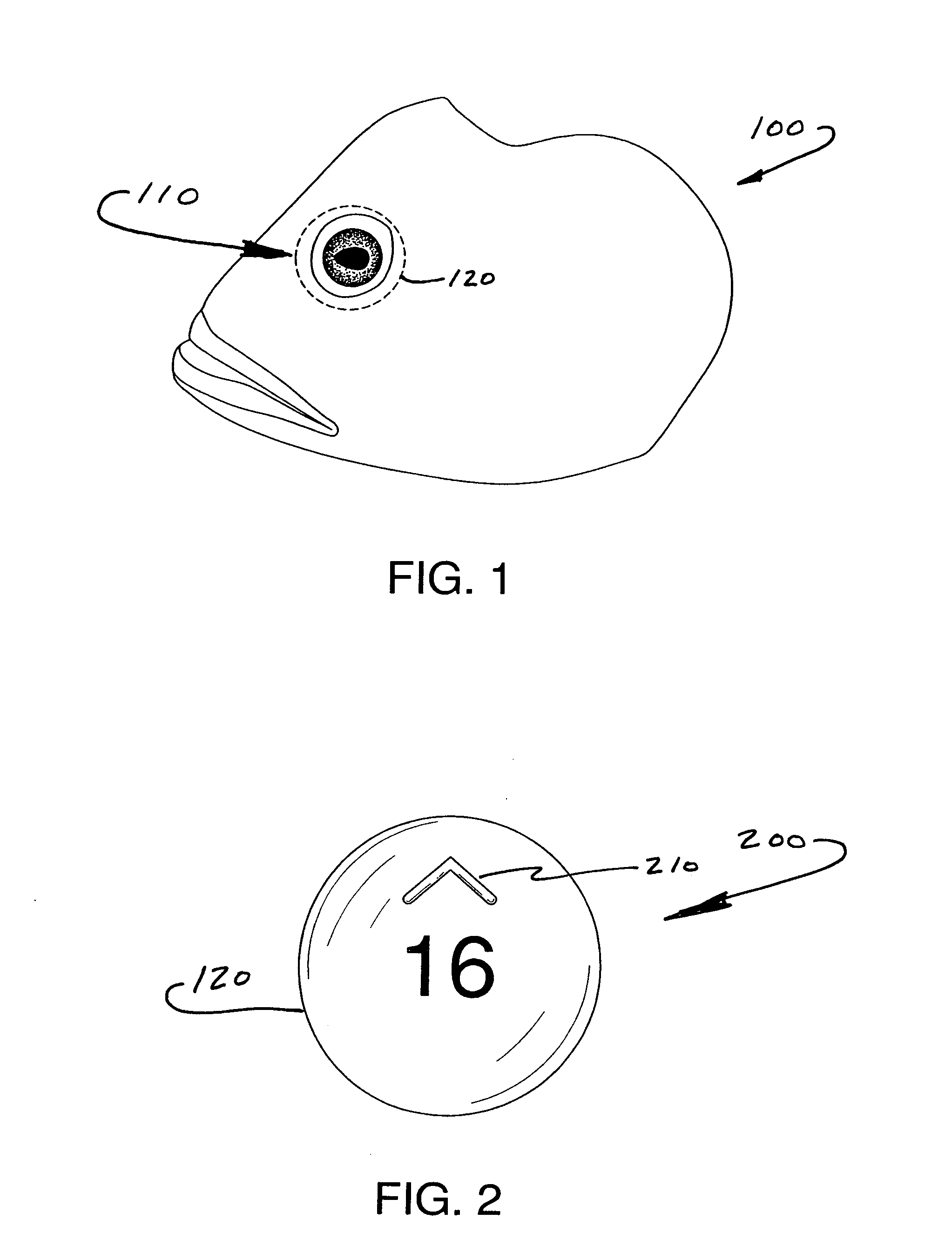
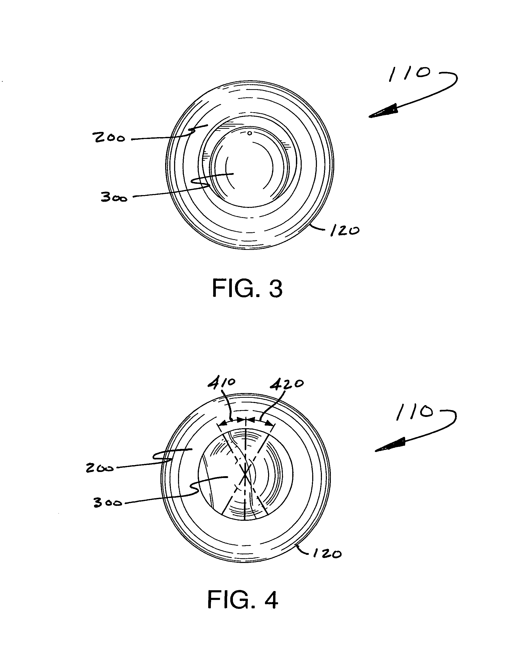
[0042]Turning now to FIG. 1 one embodiment of the eye and socket system 110 of the instant invention is depicted as being mounted to a fish head casting 100. The position of the outer edge of the bottom base of the artificial eye socket of this invention located beneath the surface of the casting is depicted in phantom as...


PUM


Abstract

An artificial eye socket for use in the mounting of artificial eye is disclosed. The artificial eye socket is of substantially unitary construction and made from a flexible material such as rubber. The artificial eye socket comprises an outer base surface; an inner base surface; a substantially contiguous outer sclera surface which extends from the outer base surface to an iris knife edge to and from an iris opening in said socket; and a substantially contiguous inner cavity surface which extends from said inner base surface to said iris knife edge to form said iris opening in said socket and a cavity within said socket. An artificial eye may be inserted into said cavity and secured in a substantially fixed position by the inner base surface and the cavity surface. Methods for manufacturing and mounting the artificial eye socket and cleaning the surface of the artificial eye are also disclosed.

Description

CROSS REFERENCE TO RELATED APPLICATION[0001]This application claims priority to U.S. Provisional Patent Application Ser. No. 60 / 906,004, filed Mar. 8, 2007, the entirety of which is incorporated herein by reference.FIELD OF INVENTION[0002]The present invention is generally directed to an artificial eye socket and method for mounting artificial eyes. More specifically, this invention is directed to an apparatus and method for mounting artificial eyes in taxidermy, doll making, sculptures and related applications, as well as the product resulting from the manufacturing process.BACKGROUND OF THE INVENTION[0003]The construction of high quality artificial manikins having life-like characteristics (such as, for example, taxidermy mounts, dolls, stuffed animals, clothing mannequins, artistic sculptures, and the like) requires extraordinary skill, and can be extremely difficult, expensive, and time consuming. Each component, such as the eyes, skin, hide, hair, teeth and the like, must be ac...

Claims


Application Information

Patent Timeline
Patent Type & Authority Applications(United States)
IPC IPC(8): A61F2/16A61F2/28
CPCA61F2/141A63H3/42A63H3/40
Inventor ALFARO, ANTONIO R.
Owner TOHICKON CORP
Why Eureka
Try Eureka